A few years ago, I bought a couple of these analog gauges(galvanometers) at the electronics flea market. Like many other things I buy, they ended up in a box stored away in the closet… Not too long ago, stumbled onto Alan Wolke’s (@AlanAtTek) video about panel meters
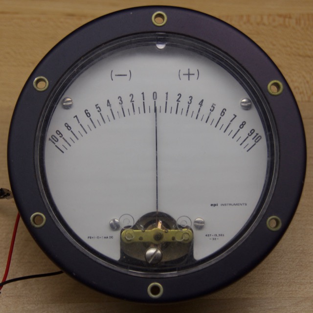
Gauge!
After watching Alan’s video, I decided to pull the gauges out and see if I could make them do something useful. The first thing I looked for after taking them out was the range. The small text on the bottom left says FS=1-0-1 mA DC. I verified this by plugging it into my DC power supply like Alan suggested with a 10kOhm resistor and going from 0-10V. Unfortunately, my power supply doesn’t go negative, so I had to reconnect the meter by switching the two wires to test the negative region.
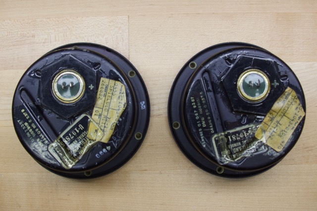
Behind the gauges
Ok, so now I have two working gauges that take -1 to 1mA to move. I’ve been working a lot with the STM32F4-Discovery development board, so I decided to use it, even though it’s complete overkill for this project. The microcontroller has two DAC outputs which can be set anywhere from 0-3V. Just add a 3kOhm resistor in series and you can move the needle from 0-10, but how can we get a negative reading?
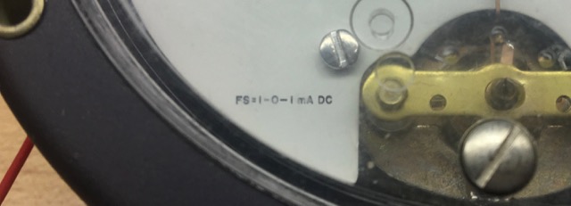
FM=1-0-1mA DC
My first thought was to use a tiny H-Bridge circuit that would connect to the DAC output and ground. This would allow the microcontroller to change direction of current flow using two digital outputs. I didn’t have any small MOSFETs around, so I tried it with BJTs. It didn’t quite work as expected. It also required a bunch of parts and 3 pins per gauge. What a waste! There must be a better way…
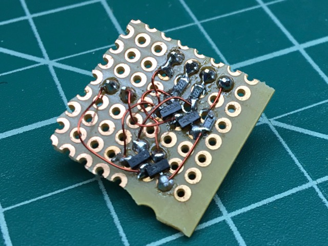
H-Bridge Attempt
After reading the STM32F407 datasheet for a bit, I found a paragraph that gave me some hope. It basically says you can provide or receive up to 8mA in any GPIO pin. This means that if you connected a resistor between two pins and drove each one high and low, you could have current flowing in both directions, as long as it was less than 8mA. The gauges only need 1mA, so it should be enough.
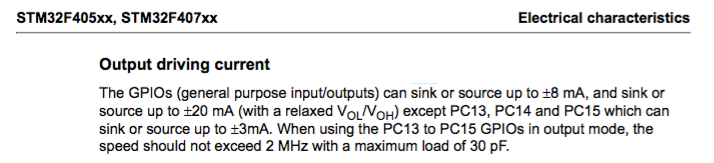
STM32F407 Datasheet Excerpt
The idea is: If I plug in one end of the gauge(plus resistor) to the DAC and the second to a GPIO, I should be able to get 1mA of current to flow in either direction.
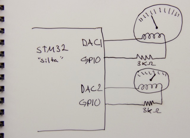
Connection Example
For example, if the DAC is set to 3V and the GPIO is set to 0V, there will be 1mA flowing from the DAC to the GPIO. If we set the DAC to 0V and the GPIO to 3, the 1mA will flow in the other direction. By changing the DAC voltage relative to the GPIO (either 0V or 3V) we can get the full range of -1mA to 1mA.
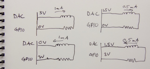
Configuration Examples
Here’s a quick video of the gauges moving around with the setup:
So there you have it, an easy, low part count, way of controlling a bidirectional analog gauge with a DAC and a GPIO pin.