7400 Series Clock
Quick Note
This was originally a Twitter thread back in March, 2020. After reading Molly White’s post about POSSE(Post (on) Own Site Syndicate Elsewhere), I’ve decided to start posting everything here and just linking from other sites. I changed a few things so it makes sense as a blog post, but the content is practically the same.
Background
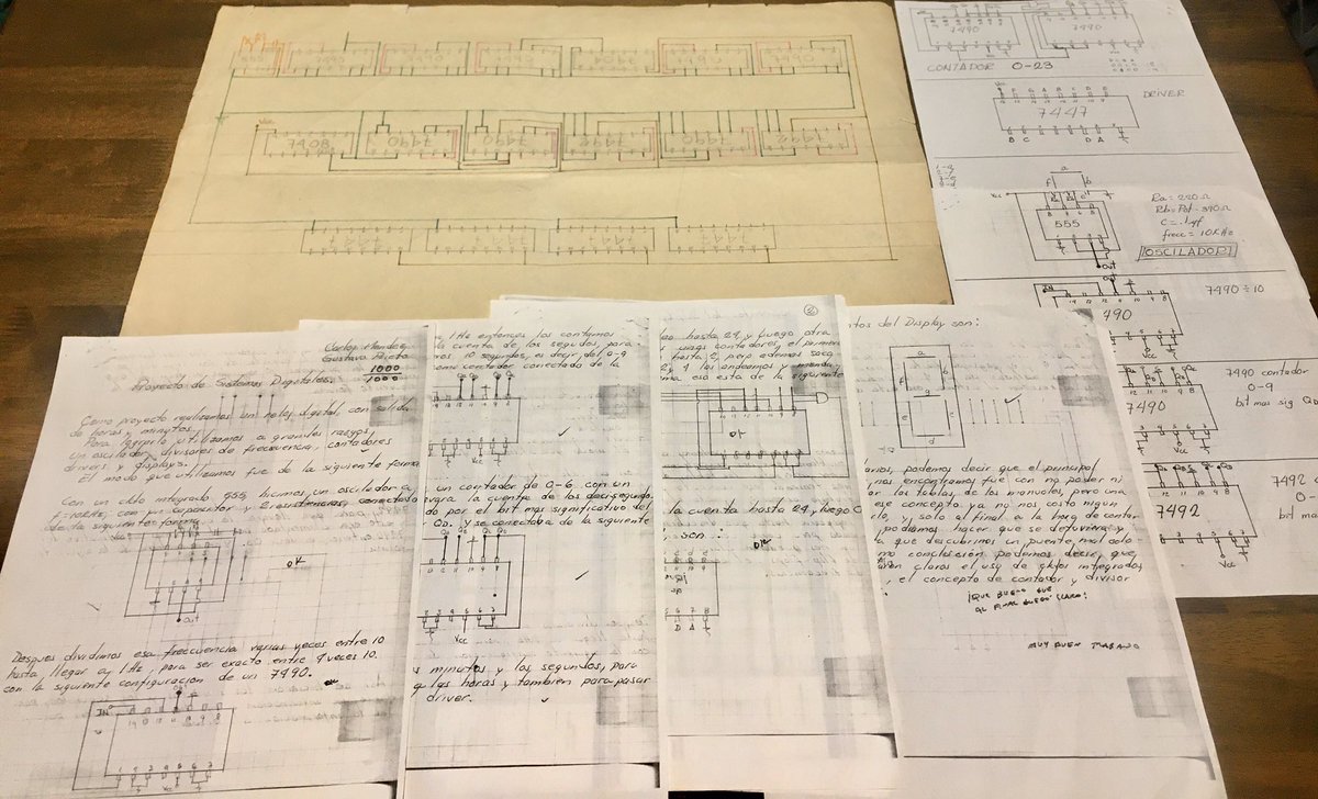
A few years ago, I found my dad’s college Digital Systems project notes. The task was to build a clock with 7400 series logic. I decided to try and re-create the project with components we bought together many years ago. You can find quality scan of dad’s project notes on github.
Overview
Below is a block diagram of the clock:
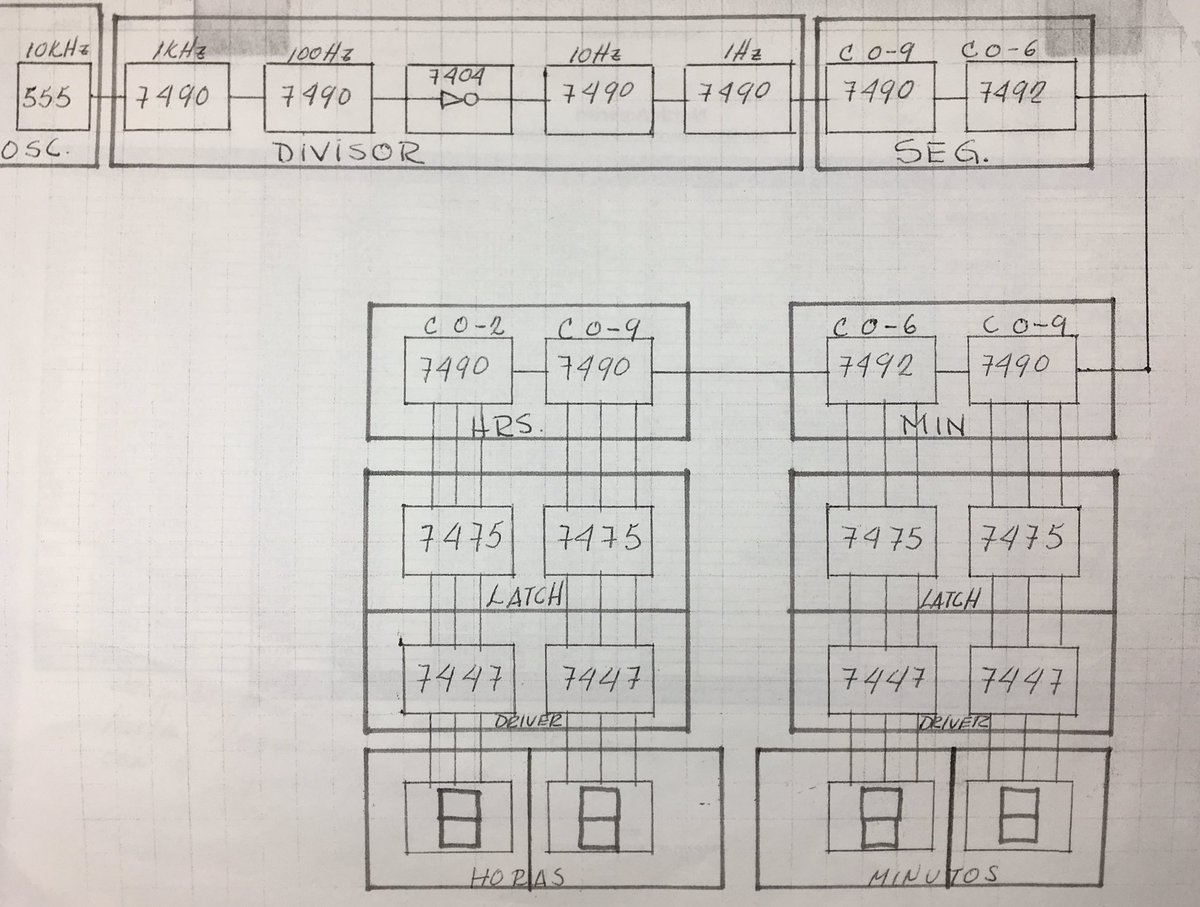
In summary, we start with a 10kHz clock, generated by a 555 timer circuit, and divide it down by 10 several times until we have a 1Hz clock. From there, we have second, minute, and hour counters, display drivers, and 7-segment LED displays.
555 Timer
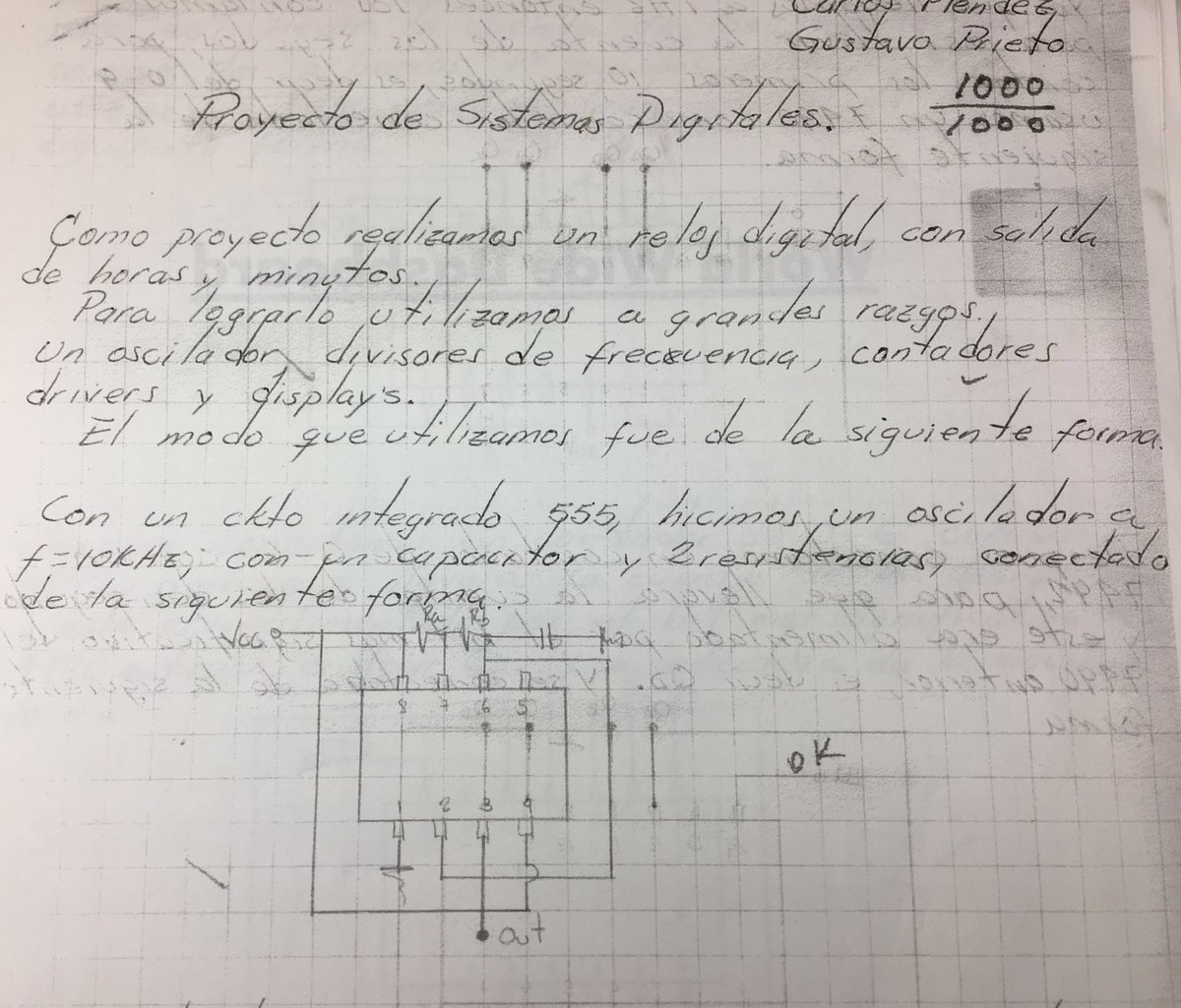
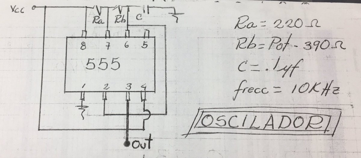
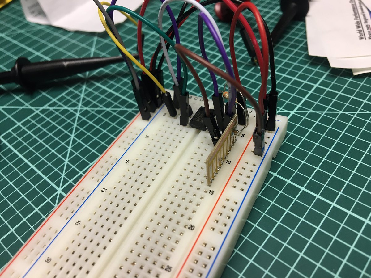
The project starts with a 555 timer to generate a 10kHz clock source using two resistors and a capacitor.
Clock Dividers
In order to divide the clock by 10, we use a 74LS90, which is a decade counter IC. In this configuration, we don’t really care about the count, but use it only to output a single pulse for every 10 pulses received.
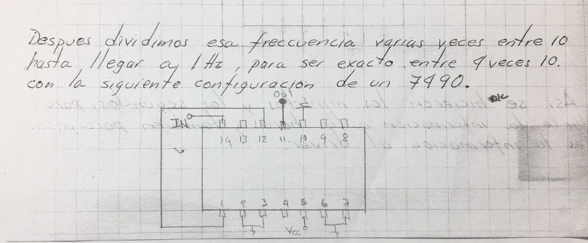

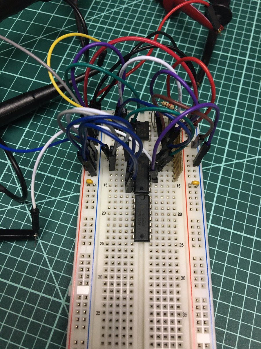
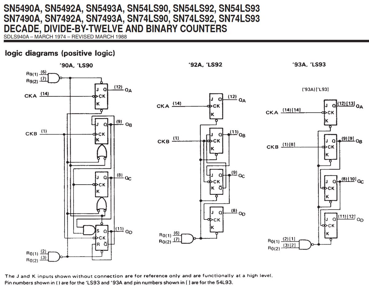
Here’s a snippet of the 74LS90 datasheet from TI. The counter has 2 clock inputs, 4 counter outputs and 4 reset inputs. In the divide by 10 case, we just connect the source clock to CKA, QA output to CKB, and QD as our /10 output. Resets are all grounded.
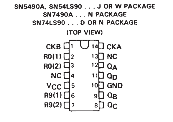
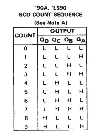
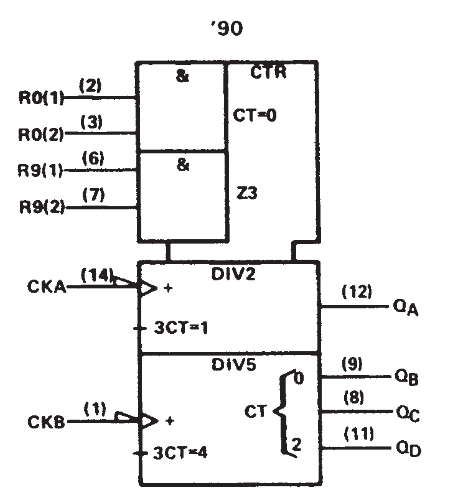
We use 4 74LS90’s to get from 10kHz to 1Hz.
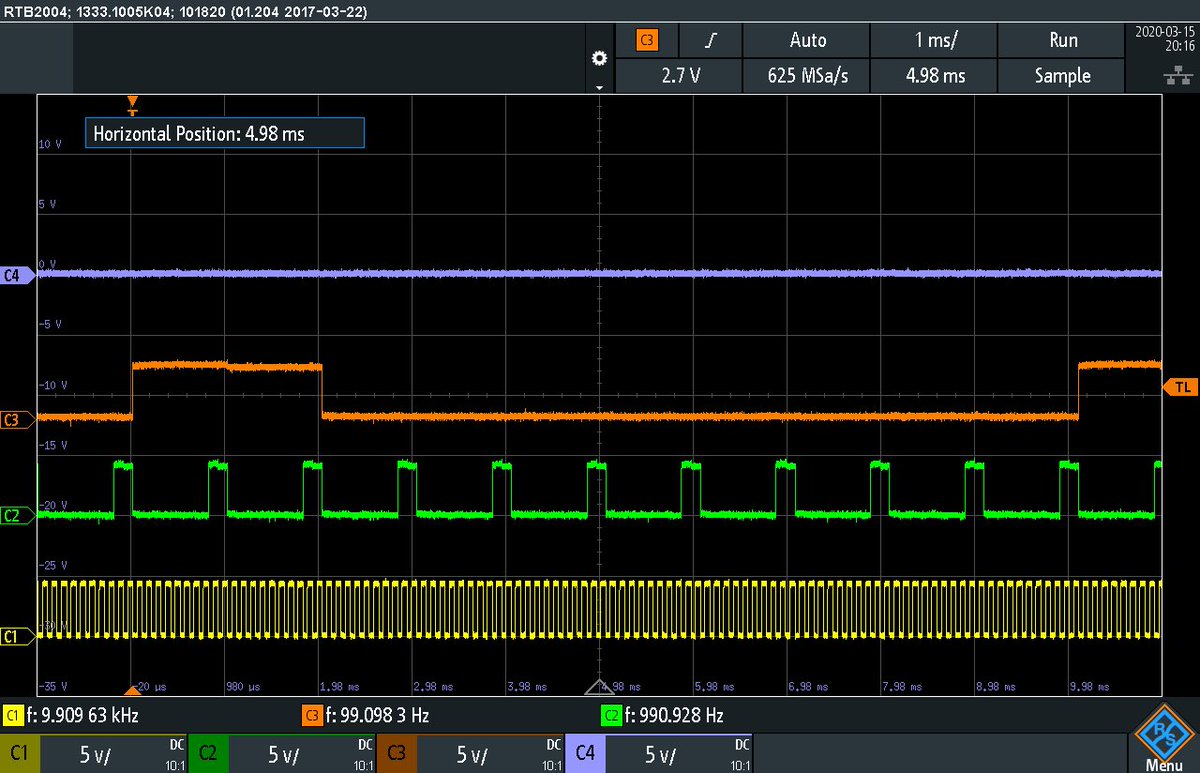
Here are some scope captures of the clock getting divided. In the first one, the yellow channel (C1) has the original 10kHz signal and the other channels have divided down versions of it.
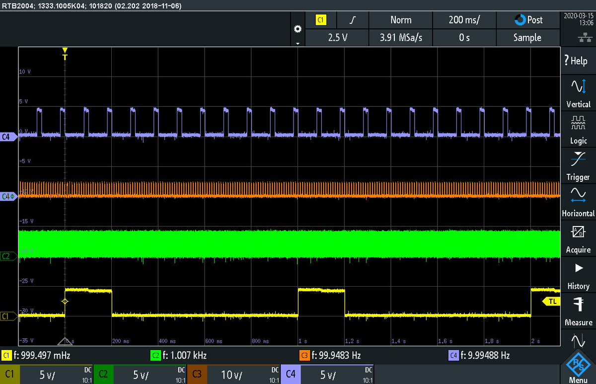
The second capture has the green (C2) channel at 1kHz and the yellow (C1) as the 1Hz output.
Second/Minute Counters
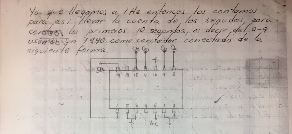
Now that we have a 1Hz clock, we can start counting seconds. The 74LS90 is again used, this time as an actual counter. This one keeps track of seconds 0-9.

For the 10’s of seconds counter, we use a 74LS92, which is a divide-by-12 counter. Why divide by 12? It makes counting up to 6 and rolling over easier (compared to the 74LS90) since it has /2 then /3 then /2. We count up to 6 then use the builtin reset to get back to 0.
Here are snippets from the TI 74LS92 Datasheet:
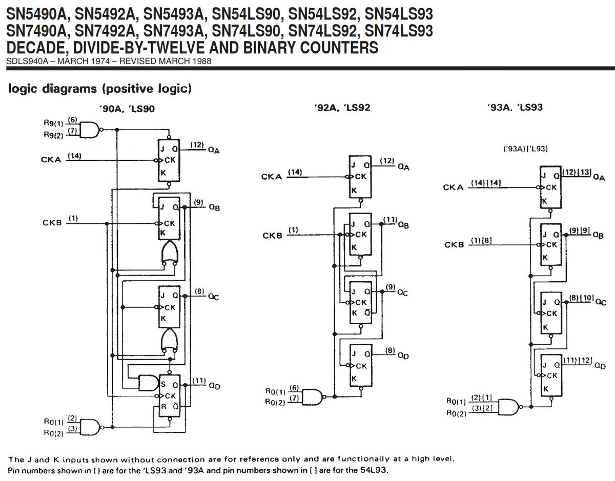
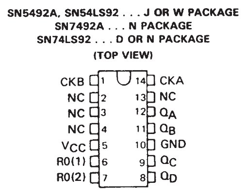
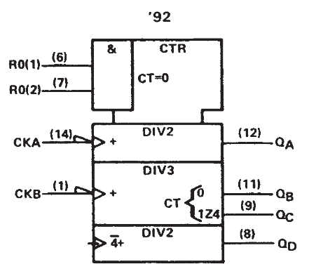
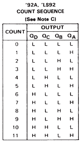
Here’s how the diagram has it connected. I think there’s a slight bug since shorting the QC and QD outputs together would not be a great idea. Simply connecting the reset lines to QD does the trick though. Once the counter reaches 6, it is reset back to 0.
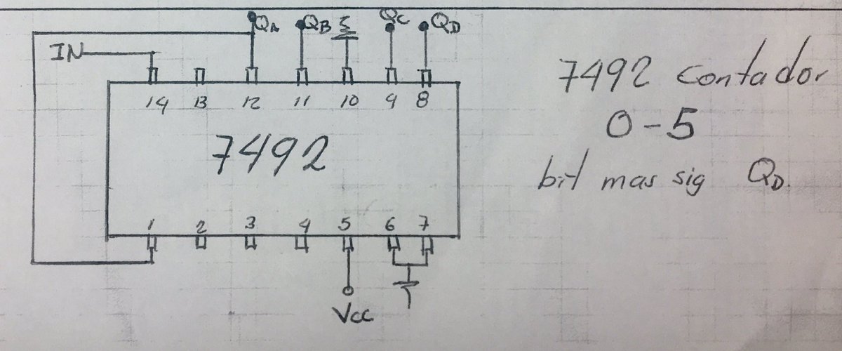
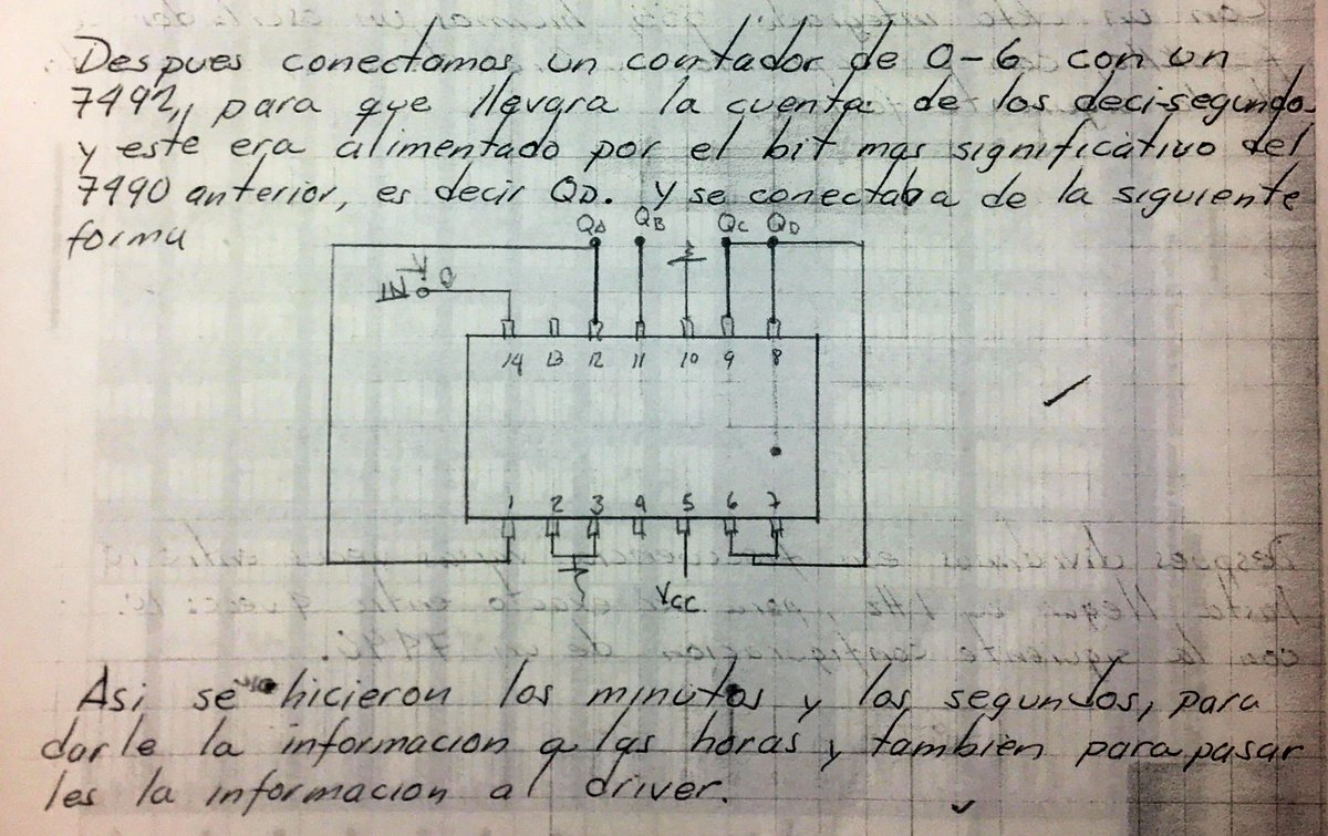
The minutes circuit is pretty much the same as the seconds. It’s clock source being the output of the 60 second rollover. Before we go to the hours counter, let’s see how the minute count gets converted into actual numbers on the 7-segment LED display!
7-Segment Displays
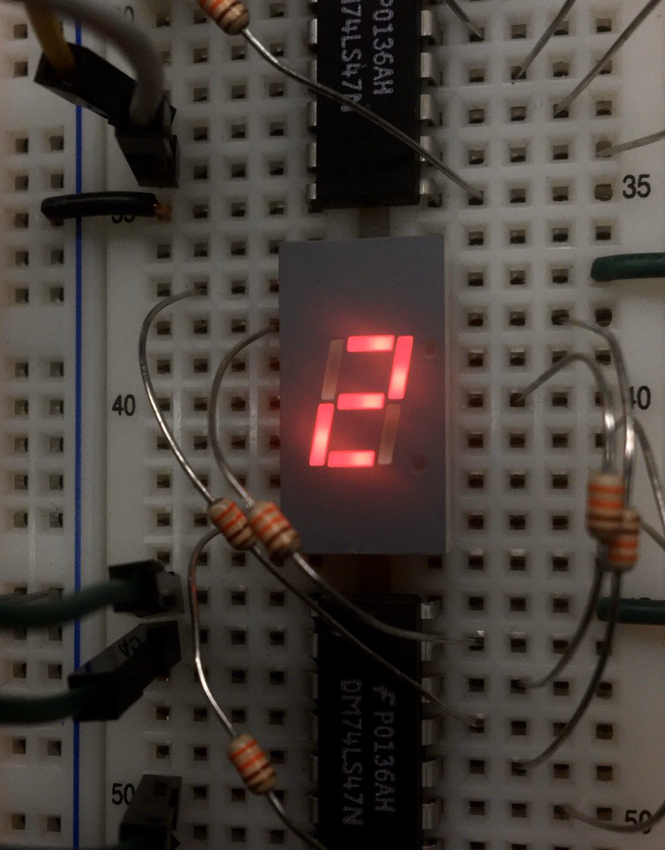
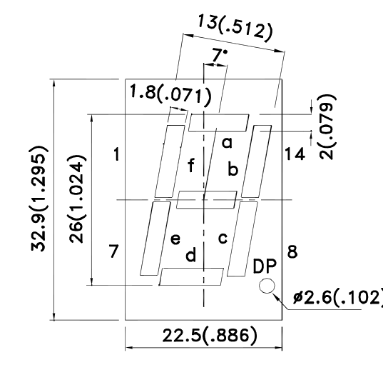
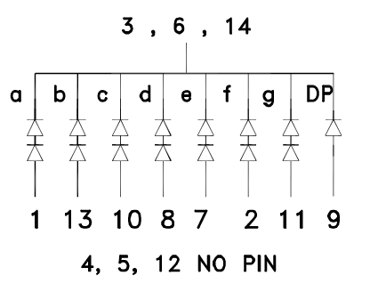
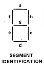
First, the 7-segment display consists of, you guessed it, 7 LED segments that can be lit up individually to create numbers (or letters!). Each segment is has a standard letter designator. In this case, all the LED’s have a common cathode to save pins.

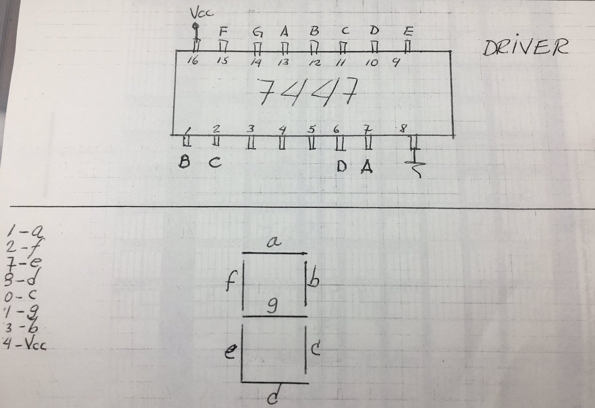
In order to convert the 4-bit output from the counters to 7-segments, we use the 74LS47 BCD-to-7-segment decoder/driver IC. It takes in the binary-coded-decimal input and converts it to a set of 7-segment outputs to light up the number. Don’t forget current limiting resistors!
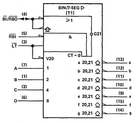
Here are snippets from the 74LS47 datasheet.
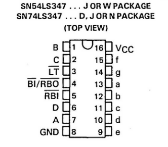
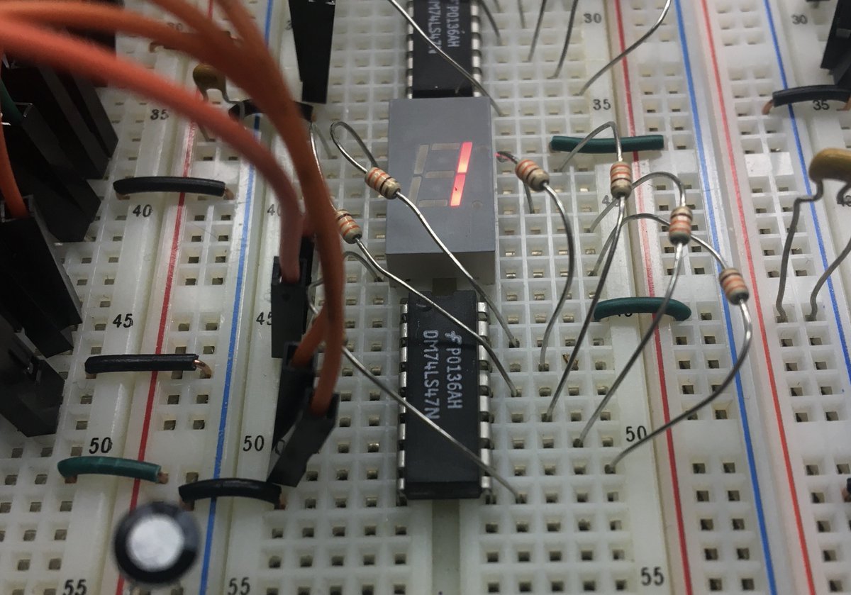
Now let’s see how we count up to 24 with two divide by 10 counters and some extra logic!
Hours Counter
In order to count to 24 hours, two 74LS90’s are used. The special part is how to get them to roll over at 24. In this case, an AND gate is used to assert the counter resets when both QB in the 10’s of hours counter and QC in the hours counter are both high.
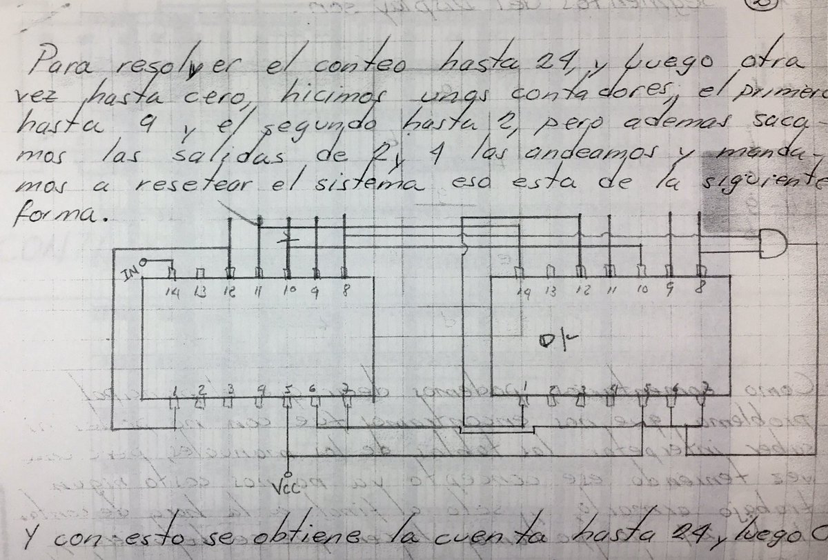
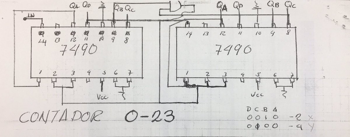
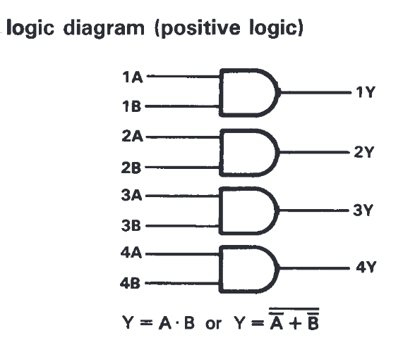
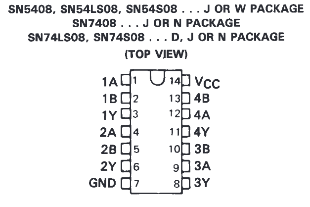
I used the 74LS08 Quad 2-Input Positive-AND gate for the 24 hour counter reset. This one is as simple as they get.
Completed Clock
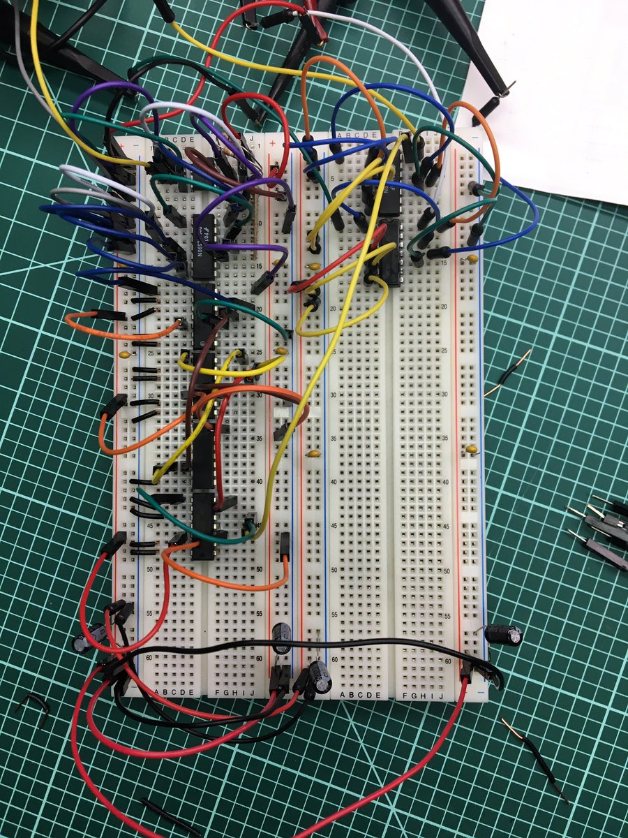
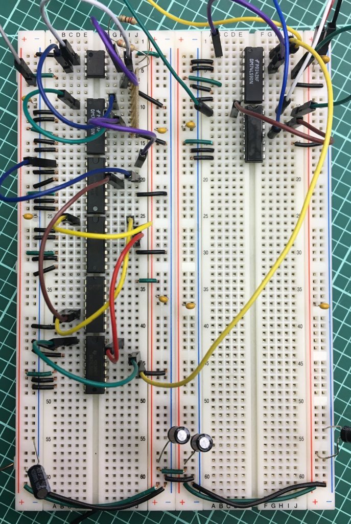
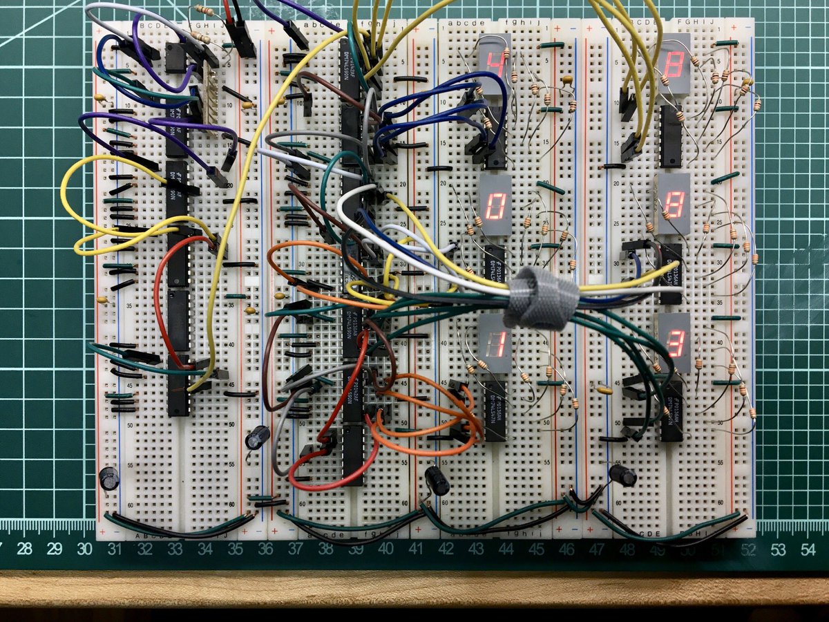
Below is a photo of a complete clock on a breadboard following the original design (with the addition of seconds display).
Here’s a quick video of the clock working. I change the clock source from 1Hz up to 10kHz to speed things up a bit.
{% include youtube.html id=“A3zyAr6v9hQ” %}
f you’re curious about other 7400-series IC’s, check out this list on Wikipedia: Shout out to bitsavers.org and the Internet Archive for scanning and hosting all the original datasheets/databooks!
Going Further
I completed the breadboard circuit in March 2020. As you probably remember, we were all stuck at home during that time. A month or two later, while still at home, I started thinking… You know what would make a great father’s day gift? A soldering kit for my dad of a circuit he designed around 40 years ago! So I started up KiCad and got designing…
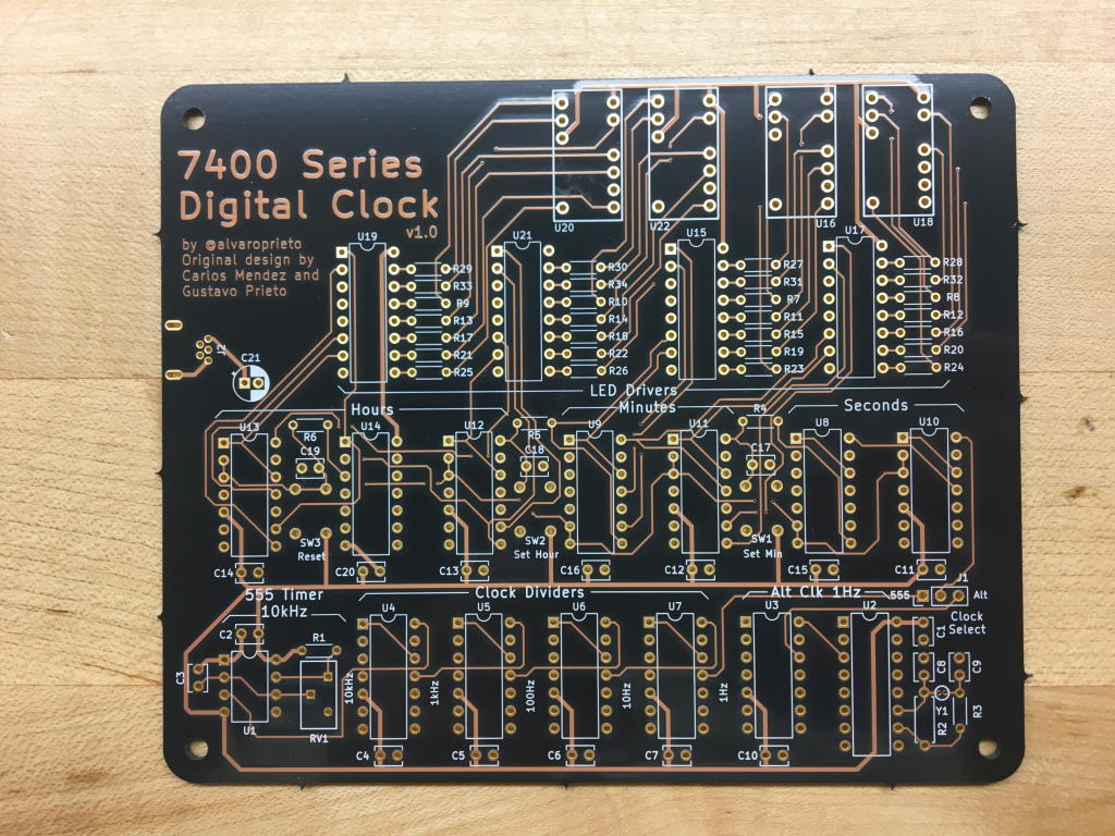
This was around the time OSHPark started offering their “after dark” PCB’s, which seemed perfect for this project. Once the board arrived, I got all the parts and started soldering.
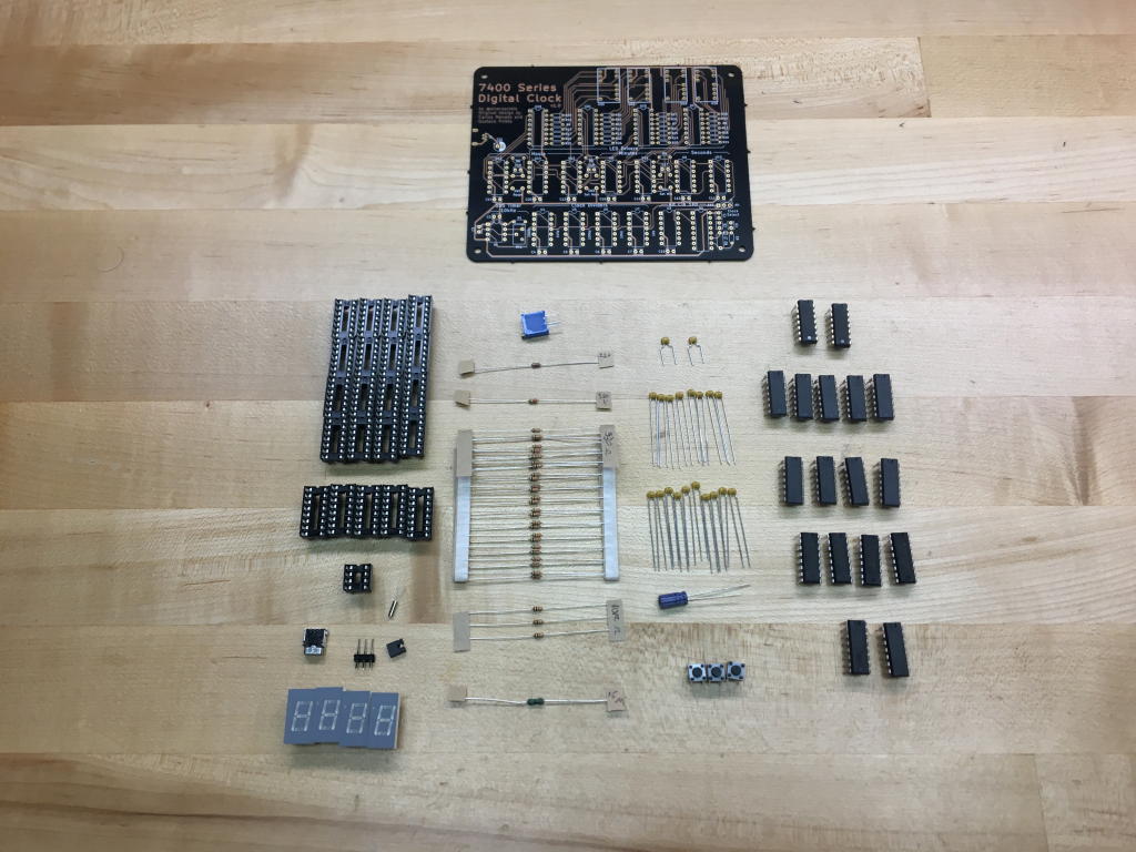
As with any v1.0 product, there were many issues… Looking back at my github commit history, here’s what I changed:
Removed global reset button.
Connected tens of minutes and tens of second counter resets to their Q3 output via RC filter. This prevents them from resetting themselves before clocking the next device.
Reduced resistor for CLK_MIN and CLK_HR so that the buttons can still overpower it.
Moved USB connector to other side and added silkscreen note
Updated reference designators to make a bit more sense
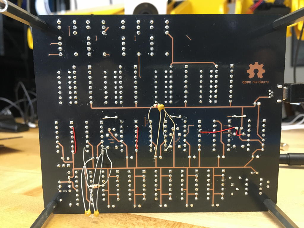
I didn’t trust myself not to have made yet another mistake, so I used a local PCB house to get quick turn boards with no soldermask.
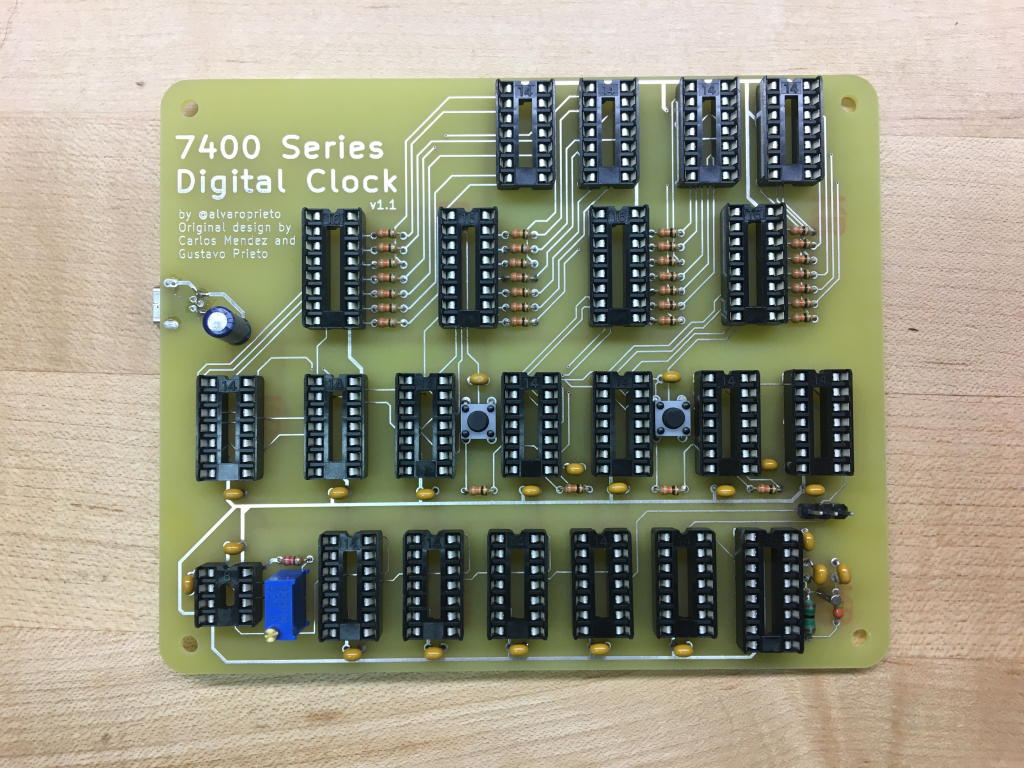
It almost worked… I still had to remove some components, cut a trace, and add a bodge wire. Here’s that commit message:
Connected U12's R0 to H_RST. Hours were going from 23->04 since the single digit hour wasn't resetting :/

Removed both 0.1uF capacitors from CLK_MIN and CLK_HR... Not sure why they ended up there. I'm guessing I was thinking of debouncing but they are clock lines so the IC's were behaving poorly.
At this point, I was confident enough and re-ordered the really nice boards from OSHPark. They looked great! Here’s the final result:
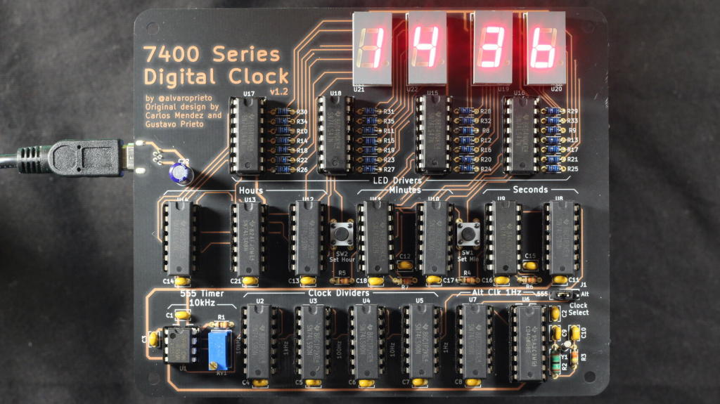
I wrote up some instructions with pictures and mailed my dad his new soldering kit. It now lives in my parent’s kitchen :)
The design is open source and all information can be found in the project’s github repo.