I recently migrated my blog from blogger to WordPress. The migration was extremely easy with the automatic importer in WordPress. The only problem is that every single link on the web is pointing to the blogger generated permalinks, which do not match the new WordPress ones.
Since I still get some traffic from other sources, I decided to come up with a method to have the old links redirected to the correct new ones. If you have a list of the old url and the new url, you can use apache’s mod_rewrite to automatically redirect the pages without the user ever noticing. The problem here is coming up with that list of equivalent urls without spending hours doing it by hand.
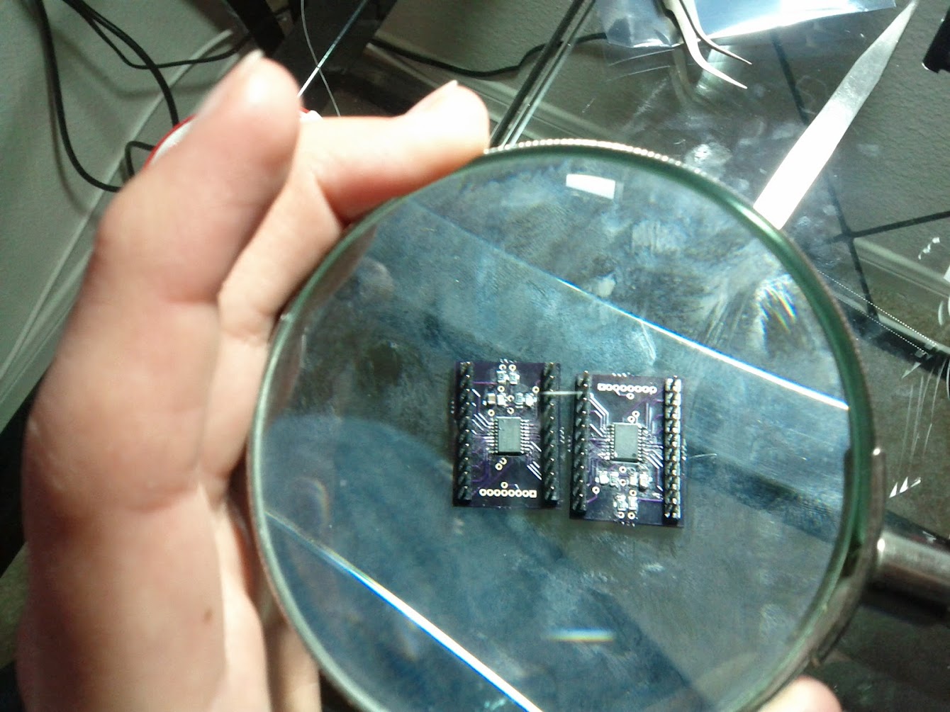
I received my PCB’s yesterday (From Laen at dorkbotpdx.org, of course!). I spent last night attempting to solder all the surface mount components (and for the most part, failing miserably). I need to get some solder paste and a small oven for the next batch…
After soldering all of the passive components and msp430’s, I began the first set of tests. First I checked to see if all of the connections were good with my multimeter. Once I fixed any problems I found there, I tried powering the board and connecting with the programmer/debugger. Surprisingly, it worked almost immediately! (I had to connect power to the correct pins first…)
Here’s another quick update (with lots of pictures and a video!) I ordered another RGB LED strip from adafruit in order to test how my system works with multiple devices. I don’t have my PCB’s yet (I shipped them to NY by mistake…), so I had to build everything on breadboards.
The main problem with my previous design is that it required two separate power supplies. The LED strip runs off 12v, while the microcontroller and radio run at 3.33v. I had a couple of MC34063A DC/DC converters laying around, so I figured I’d make a 12-3.3v converter. I also had an LD33V linear regulator, so I decided to try them both.
My current apartment has one of those ‘smart’ electric meters that can communicate with the power company directly over the power lines. A few months ago, I found out about a smartmetertexas.com, which lets you register and get logs of your power usage in 15 minute increments. I thought that was really awesome and signed up. The concept is really cool, but unfortunately, their user interface isn’t that great. It does, however, allow you to export all of that information in one large csv file.
I managed to go flying last Friday after work. Since no one else was able to come along, I decided to do some experiments with the camera.
Last time I mounted the camera on the rear window pointing out. This time I pointed it toward me, instead of out the window. I did a time-lapse of the first half and later on an actual video of the landing.
Not too interesting, but I figured I would share them here.
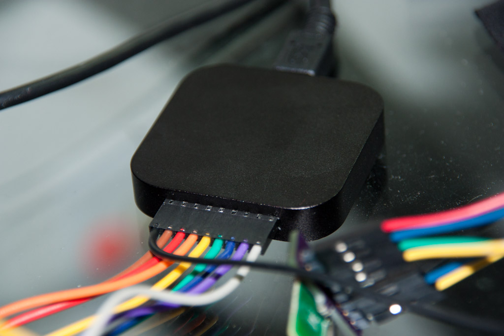
So I wrote last week about getting UART working on the MSP430G2533 but having major problems with the SPI interface… I was so frustrated that I caved in and purchased a Salae Logic analyzer. It finally arrived today, and I had a chance to test it.
As soon as I opened the box, I connected it to sniff the SPI lines between my msp430 and cc2500 radio. It took me maybe 10-15 minutes to set up everything, including the Salae software to decode SPI on the fly. I ran my radio-setup code and observed the logic output. It seemed like something was happening, but it wasn’t quite working.
This post is mostly about software, so I’ll keep it short.
I re-arranged most of the code so it hopefully makes more sense. My goal is to make the main code hardware agnostic. That way if you want to use a different device, you just change which drivers you’re using, but your main code stays the same. Eventually I’d like to be able to support multiple devices from multiple manufacturers.
I haven’t been working on this project lately, but I finally got back to programming yesterday. I got the MSP430G2533 which has both hardware UART and SPI. This one will act as a bridge between the PC and the CC2500 radio. It could also be used to drive a serial LCD.
I managed to get the UART working, but for some reason I’m having trouble with the SPI communication with the radio. I’ve been wanting to get a Saleae Logic analyzer for a while. Now I have a reason!
Since the MSP430G2452 doesn’t have a hardware UART, it’s not very useful in communicating with the computer. I could use the bit-banging method to get 2400baud, but I didn’t feel like figuring it out.
For my thesis, I implemented a serial-to-radio repeater using the EZ430-RF2500 and a USB-to-serial converter. I was able to modify the code to get it working. It ends up being a 19200baud link. For some reason, I can’t get the processor to run at 16MHz without it giving me problems. Since I don’t wan’t to figure those out now, I’m running it at 1MHz, which prevents me from doing the usual 115200baud. (Not that I really need that speed.)
Today I was able to get the radio libraries working better and actually set up constant radio communications across a room. I also wrote an RGB led controller using PWM and combined them together.
Here’s a brief video of the result:
So far it’s just one microcontroller generating RGB values and sending them to another one. Now I need to work on getting the PC to talk to the first microcontroller so I can control the lights with my computer.