J-Link Compact USB-C Issues
Do you have a J-Link Compact and have noticed it doesn’t work with some USB C to C cables? I do, and I did, so I decided to investigate…
Background
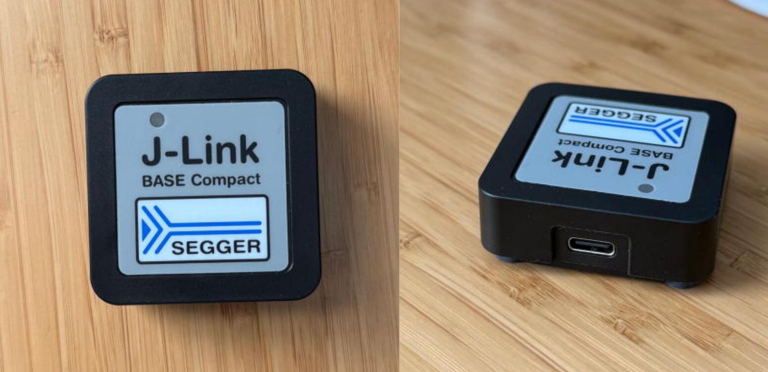
The J-Link Compact is a really nice debugger for various microcontrollers. The non compact version is rather large and uses USB-B(or Ethernet). It comes with a branded ~1m C to C USB cable, which works great. I plug it into my laptop, the green LED turns on and I’m ready to debug!
One day, I needed to reach a device that was more than 1m away, so I grabbed a 2m macbook charging cable and plugged it in. It didn’t work. The light didn’t turn on and the device didn’t enumerate. I immediately tried another cable and it didn’t work either. The original cable worked, but none of the long ones did. I tried a long USB A to C cable, and it worked just fine… That gave me a hint to what the problem could be…
Investigation
Type-C Detour
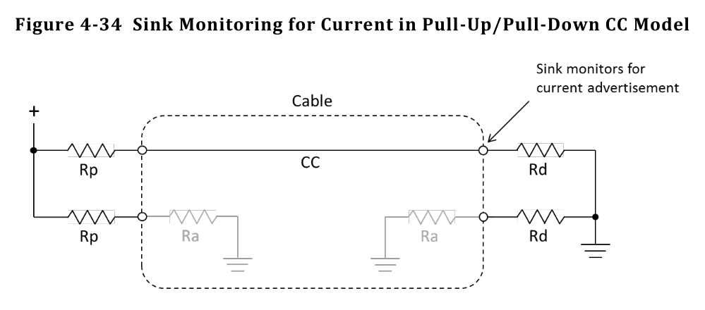
The fact that some type-c cables work but not others strongly points to issues with the CC pull down resistors. To understand what that means, we need to look at the USB-C specification. In short, all USB-C cables connect one of the two CC lines between host and device. The sink/device must have a 5.1kΩ pull down resistors on each of the CC lines. The host has a pull up whose value depends on how much power it can source. The second CC line remains disconnected and both devices can use that information to determine cable orientation, among other things.
The figure below(from the USB spec) shows a schematic of the connection. For most “basic” USB 2.0 cables, Ra is not there and the pin is effectively left floating.
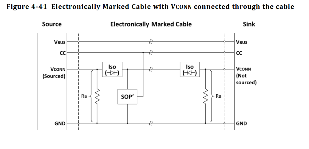
 That basic resistor configuration is enough for a device to advertise up to 5V@3A of power. Devices can further negotiate for more power using the PD protocol, but to get the maximum power available(over 3A and up to 48V) requires the cables to be “electronically marked” or eMarked. This means there’s a small microcontroller inside the cable with information on the cable’s capabilities. This is also required for “full featured” Type-C cables like Thunderbolt and DisplayPort.
In order for the host to know it has an eMarked cable connected, a 1kΩ pull down resistor is present on the second CC line, also referred to as VCONN. The device can then power the microcontroller and talk to it over the CC line.
The Cables
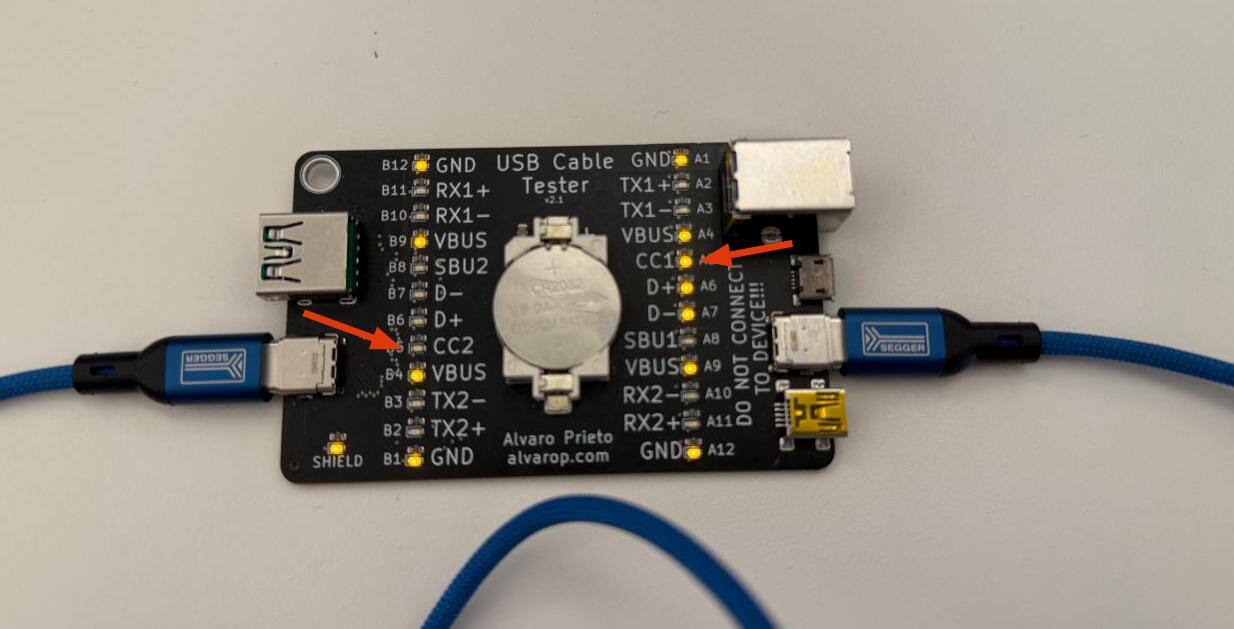
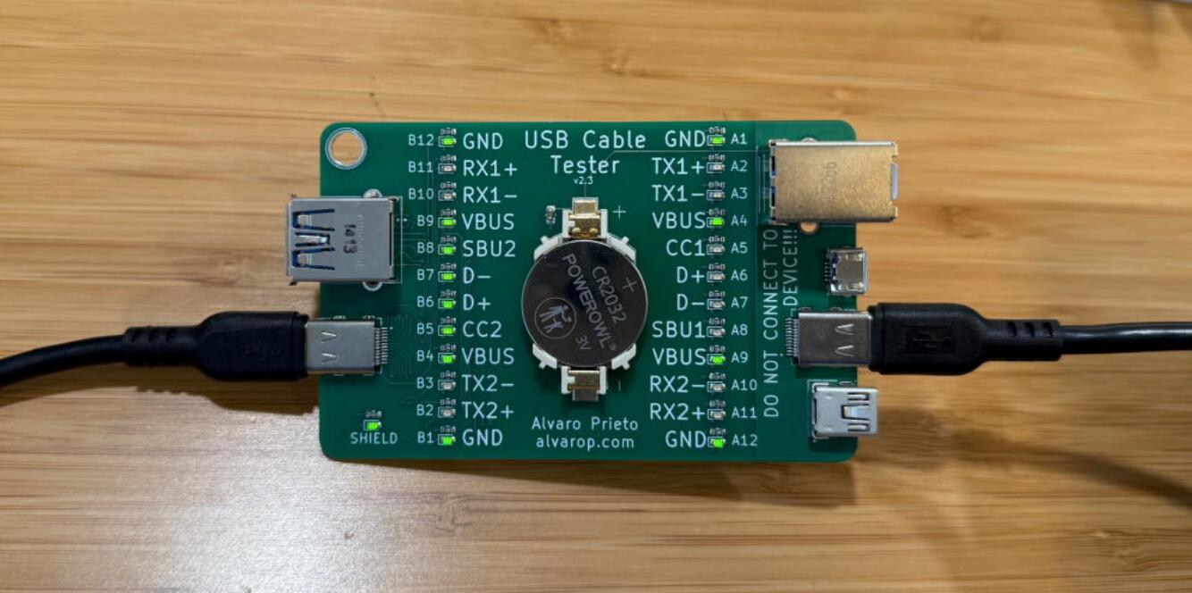
In order to test my theory, the first thing I did was pull out my trusty USB Cable Tester and tested working and non working cables.
First, I tested the included cable. It looked OK.
I found another cable that worked, and it looked OK too. The only reason the signals don’t exactly match the one above is just the orientation of the cable.
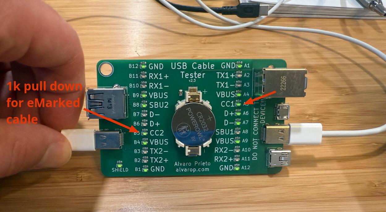
Finally, I checked the macbook charging cable… Aha! Both CC lines are lit up. CC2 isn’t actually connected to the other side, but since it has a 1kΩ resistor to ground, the LED lights up, a little dimmer than the rest.
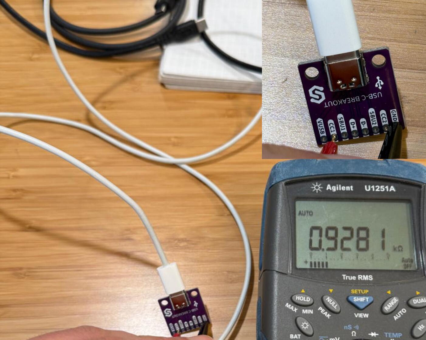
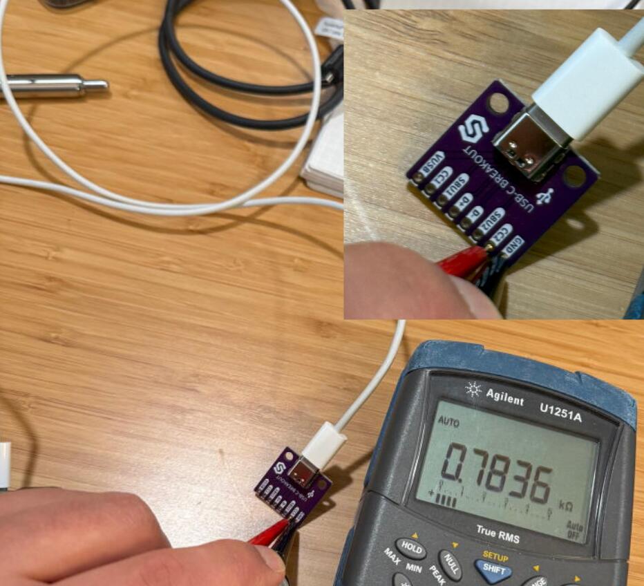
 I verified this with a breakout board and a multimeter.
The Device
In order to measure the CC pull downs of the J-Link, I used a breakout board I had around from my SWD to USB-C project.
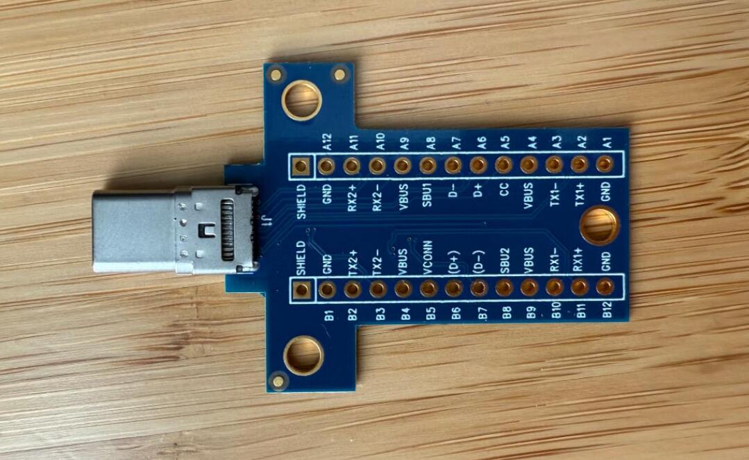 I started by measuring the resistance between the CC lines and ground. It was around 5kΩ, which is close enough to 5.1kΩ. The problem, and what I suspected was going on, is that both CC lines are connected together.
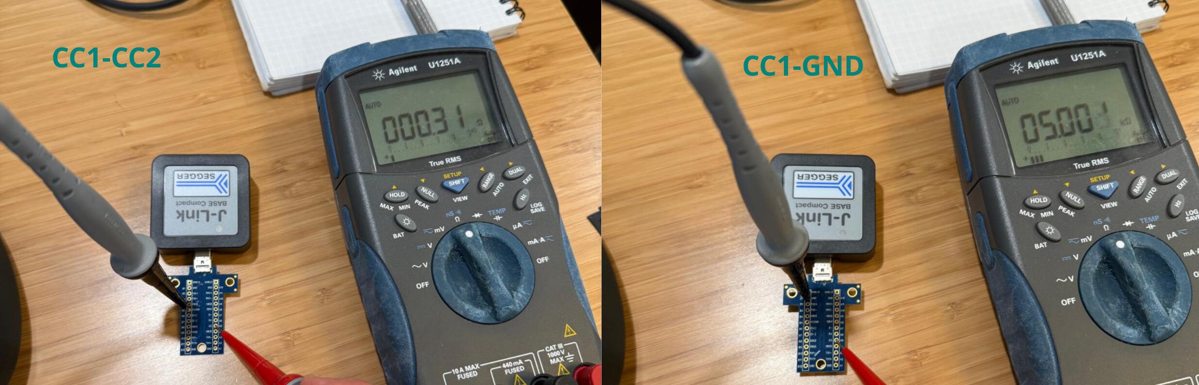
You might ask, why is this an issue if cables don’t connect the second CC line? Imagine you’re the computer that the J-Link is attached to. Before providing 5V power, you monitor your CC lines until they get pulled low. Then you check if they are being pulled low by a 5.1kΩ resistor. If both those conditions match, then you apply 5V to the bus.
Let’s see what resistance the host would get with the good cable…
CC1 looks OK.
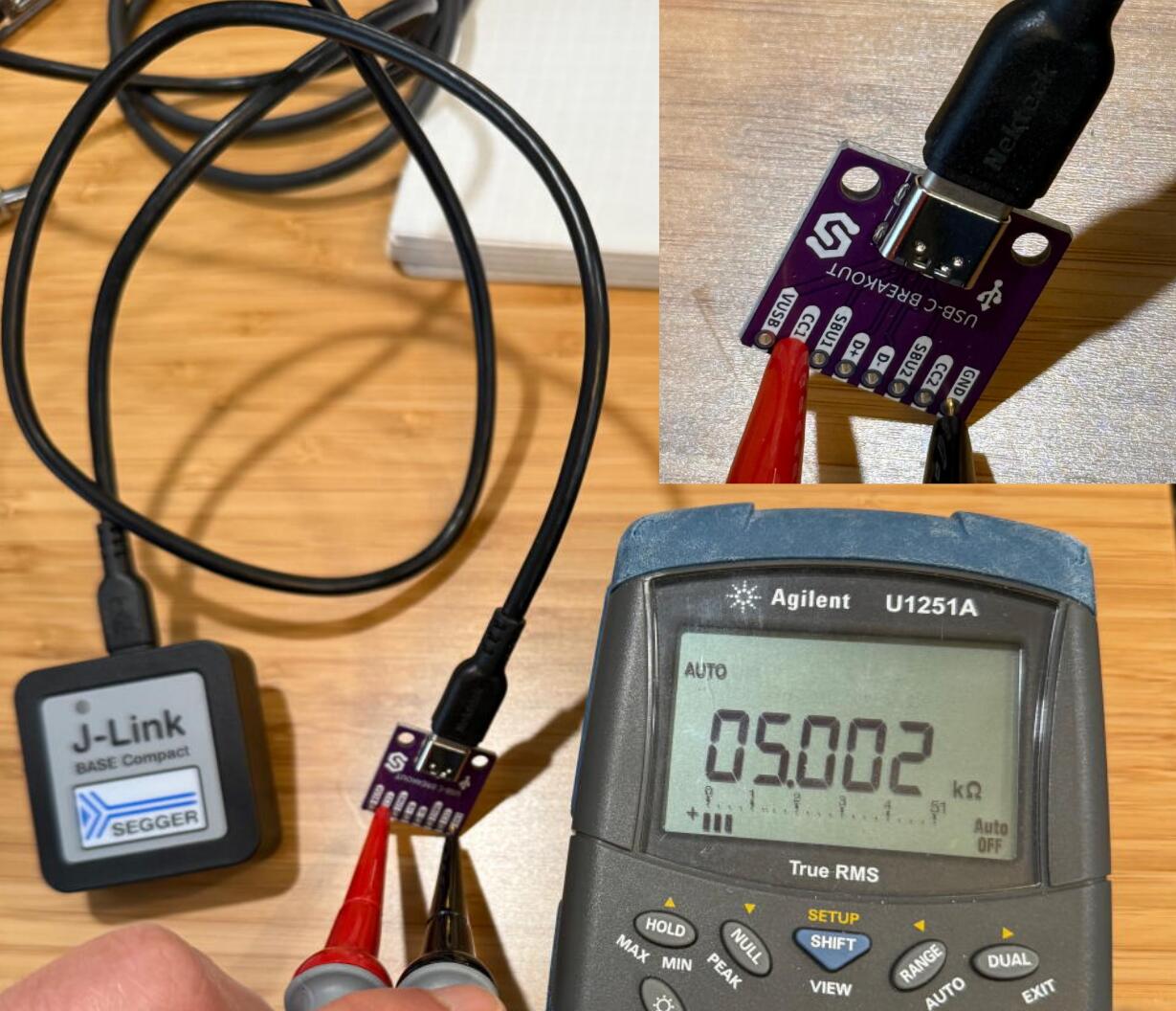
CC2 also looks OK.
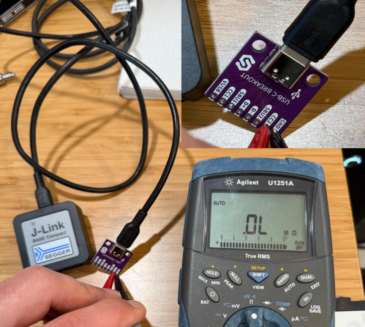
Now let’s verify with an eMarked cable.
CC1 is seeing… just under 1kΩ. This is the eMarked cable pull down on one side. Not a problem.
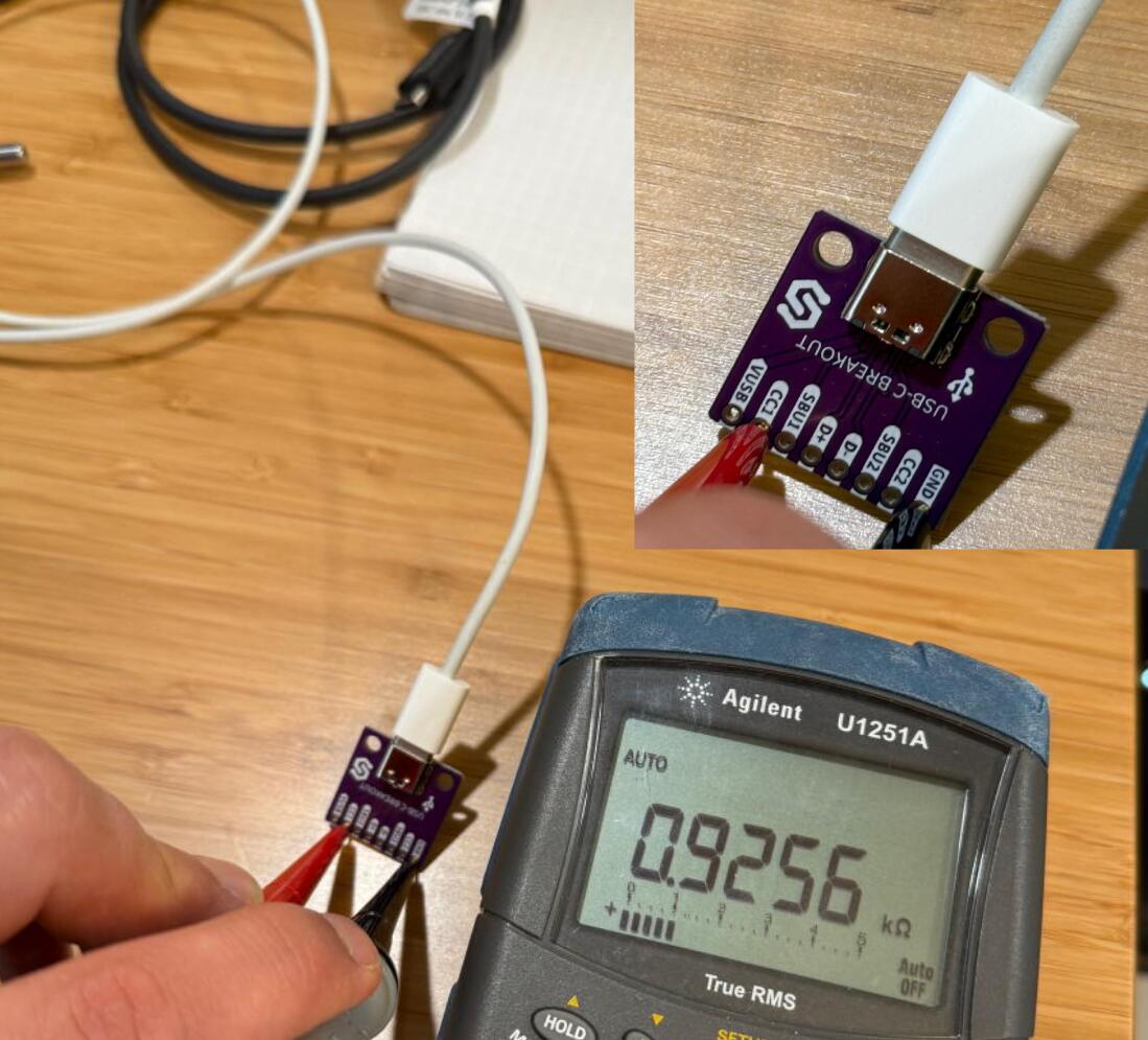
And CC2 is seeing 0.7836kΩ. That’s far from the expected 5.1kΩ, so of course the host won’t power the device!
But why?!
First, lets open up the J-Link and take a look inside.
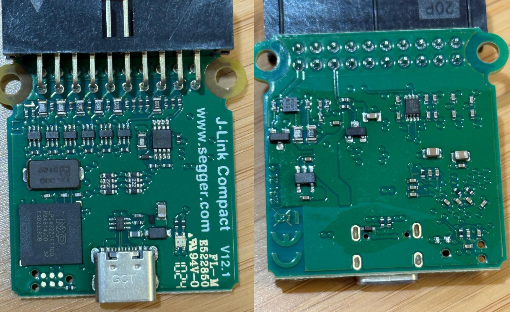
There it is. Both resistors are connected together and both CC lines are connected together. This would put the 1kΩ cable pull down in parallel with the 5.1kΩ pull down.
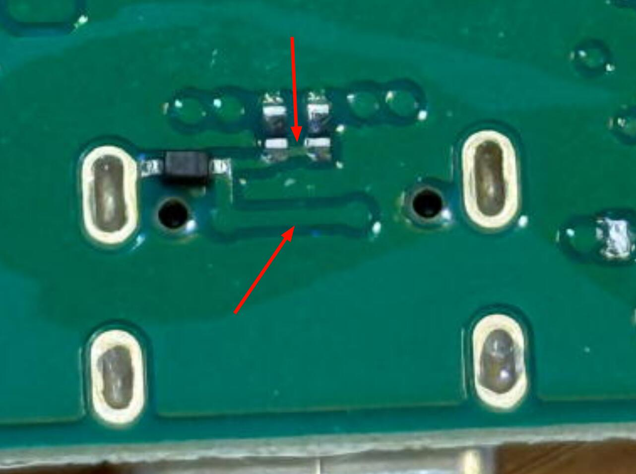
I’m not quite sure of the logic behind this. I guess they saved one ESD protection diode? But then they used 2 resistors when 1 would suffice. It wouldn’t have worked if they used two of the recommended 5.1kΩ, so they probably used two 10kΩ resistors. This reminds me about a similar issue the original Raspberry Pi 4 had with it’s power port. Take a look at the great Hackaday write up for a much better explanation.
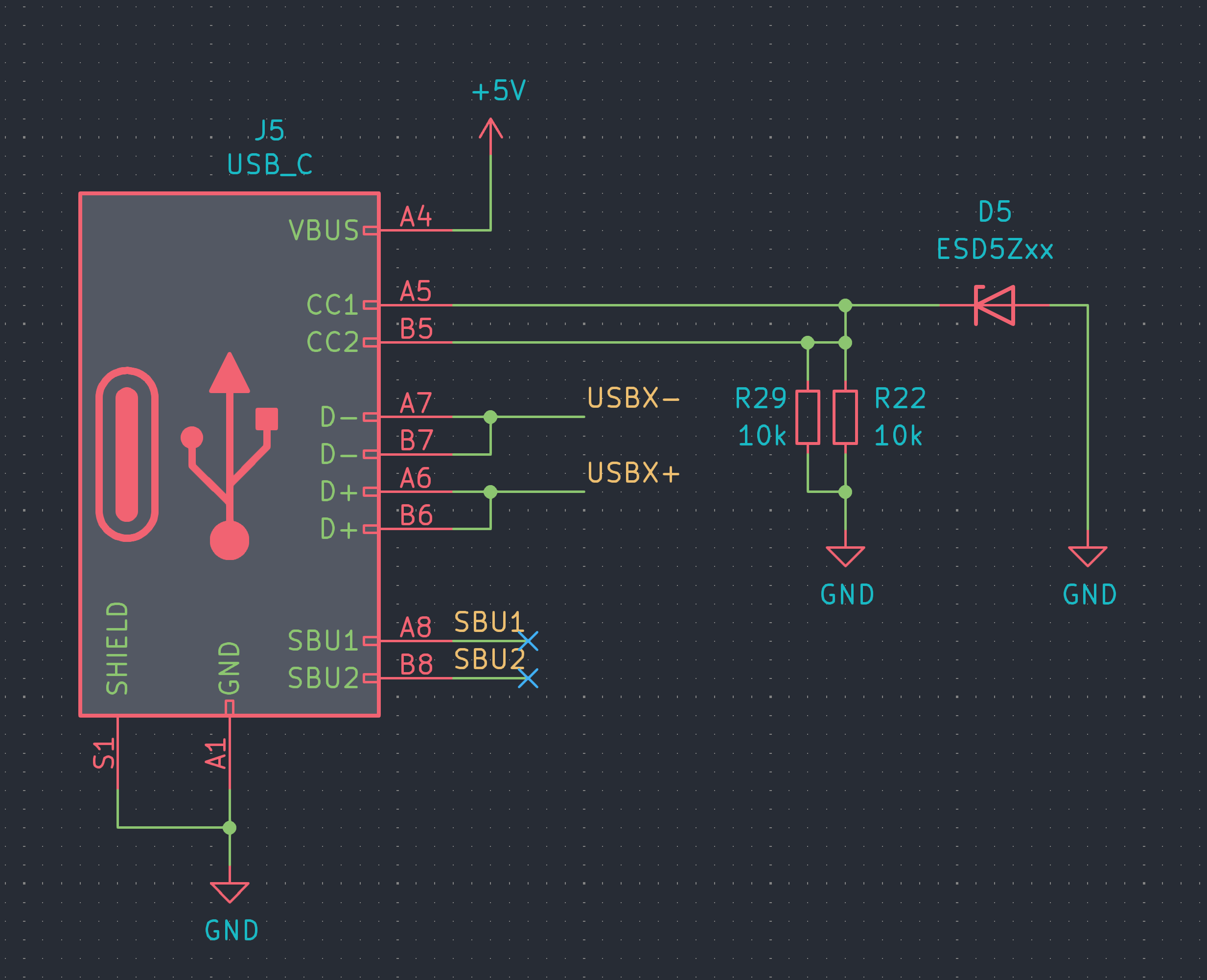
Piotr was kind enough to create a schematic that better describes the issue.
Either way, I expect better design out of a \$498 US (or \$748 for the PLUS model) device! A correct implementation would cost them a few cents at most… These days, more and more cables are eMarked and this will cause endless frustration to users. Hopefully this post alleviates some of that.
Workarounds
Don’t use eMarked cables… If you don’t have a cable tester, look for Thunderbolt/displayport labels as well as 100W/240W markings. Those will always be eMarked.
USB A to C cables will always work since the host doesn’t have CC lines to worry about on the type A port.
You could also cut a couple of traces, replace two resistors, and make one new solder joint on your J-Link, but that probably voids the warranty. 😂