Laser Turret Project - Mechanical
The last turret update (with actual content) happened back in February. I continued working on it through August, taking it both to Maker Faire and DEFCON. I had planned on writing about it back then, but never really got around to it… This post covers the mechanical aspects of the project. I’ll write about the electrical/firmware/software some other time.
The last post covered some initial progress with servos and basic software. I decided that platform was not going to work and continued experimenting with other alternatives. The next thing I tried were stepper motors. I figured having absolute position control would be useful when trying to point a laser somewhere.
The first problem I encountered with stepper motors was how to attach them to the turret. The first try involved using pulleys. I had this great tiny steppers that I thought would work great, unfortunately that was not the case. I didn’t take into account the weight of the thing, so the steppers were only able to work in one direction: towards the ground.
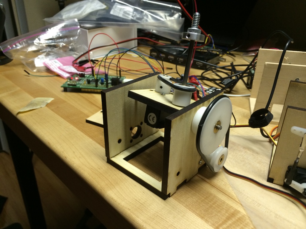
After that hurdle, I re-did the turret to be able to hold much larger stepper motors. I also decided to try something a bit stronger than the pulley and started doing some research about gears.
It turns out that gears are expensive, go figure. Unless you’re using mass produced ones made for rc cars or other similar things, the price goes up quick. Another problem with gears is that you either have lots of backlash, or need some very precise mounting so they don’t grind and jam together.
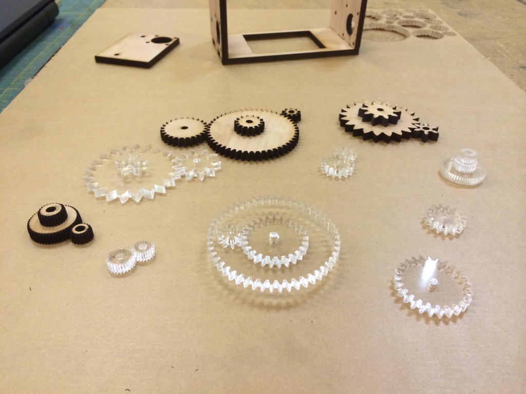
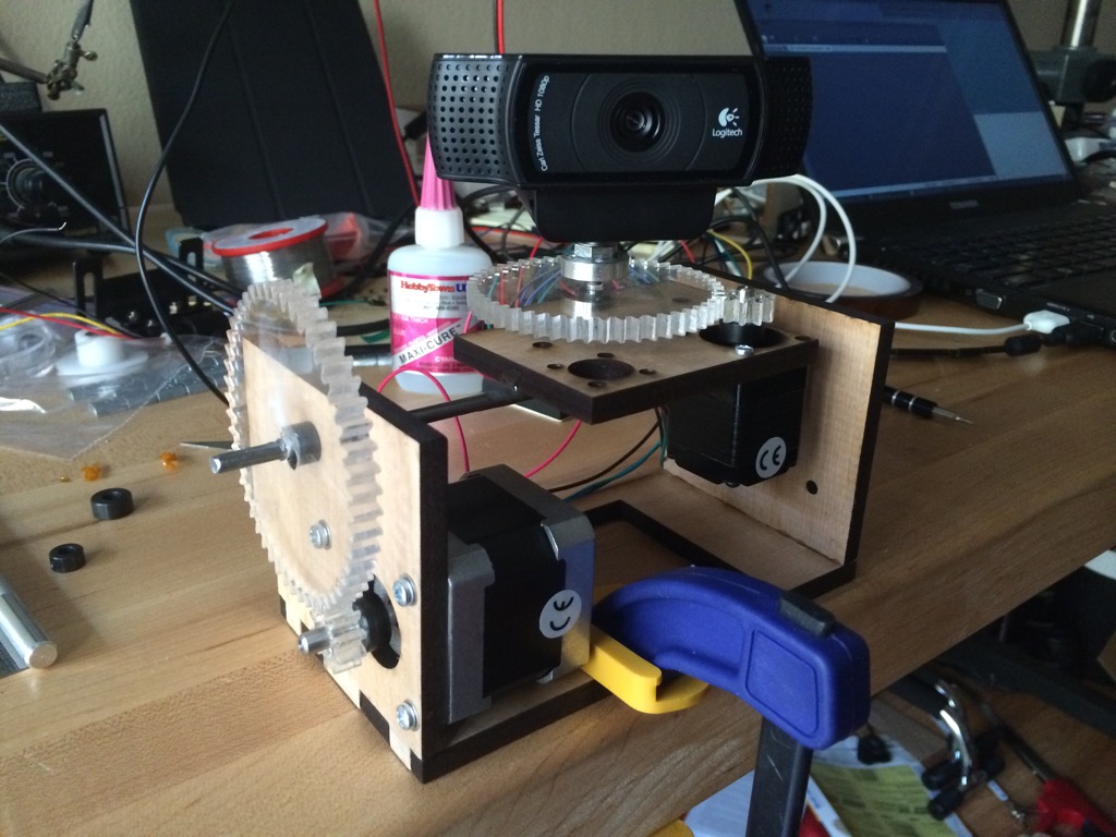
Duiring the gear research, I found some openSCAD scripts to generate gears. Since I was already laser cutting the turret, I tried making some gears too. The wooden ones started failing when the teeth were too small, so I switched to acrylic gears.
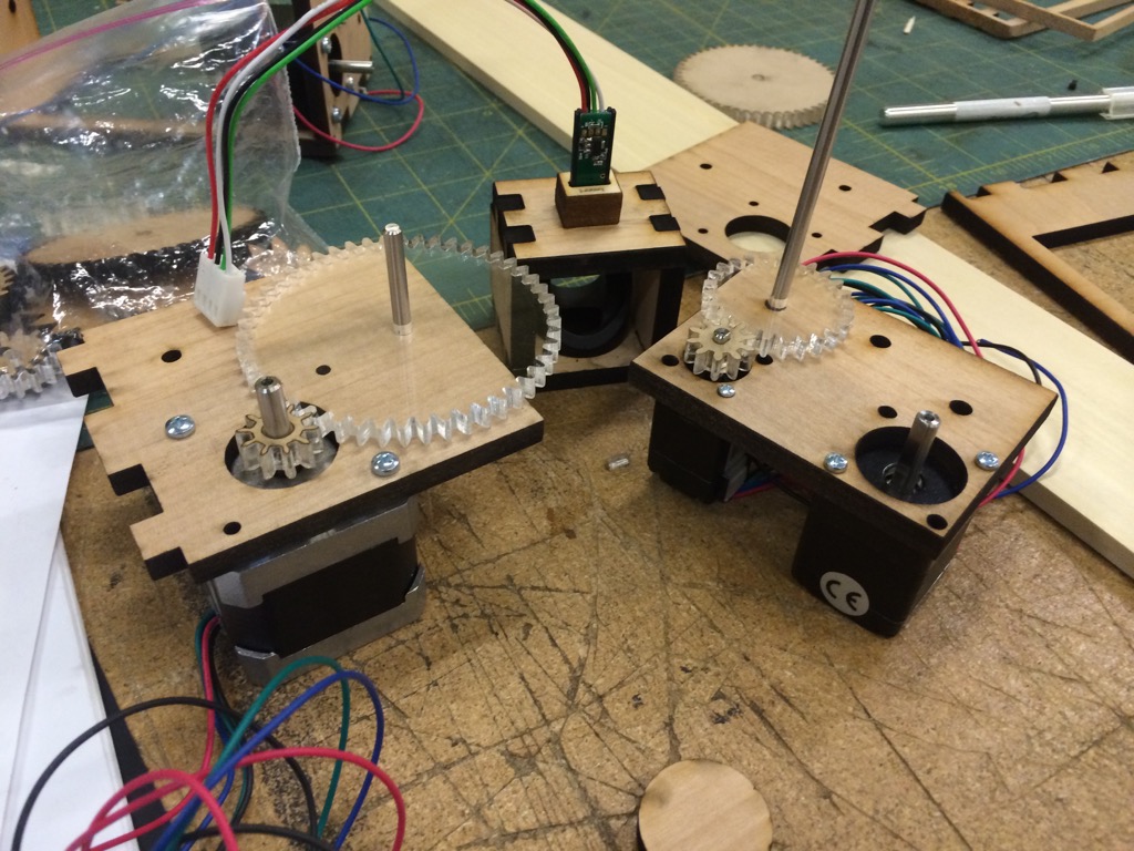
I built several test fixtures to try different gear and motor size combinations. I completely underestimated the size of the stepper motors I would need with the large webcam, so I had to order some larger motors. The final stepper motor design worked fairly well. The normal 1.8 degree steps were way too coarse, so I had to enable micro stepping. Combining that with the gears resulted in fairly decent resolution.
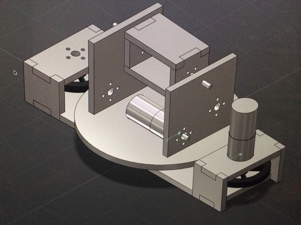
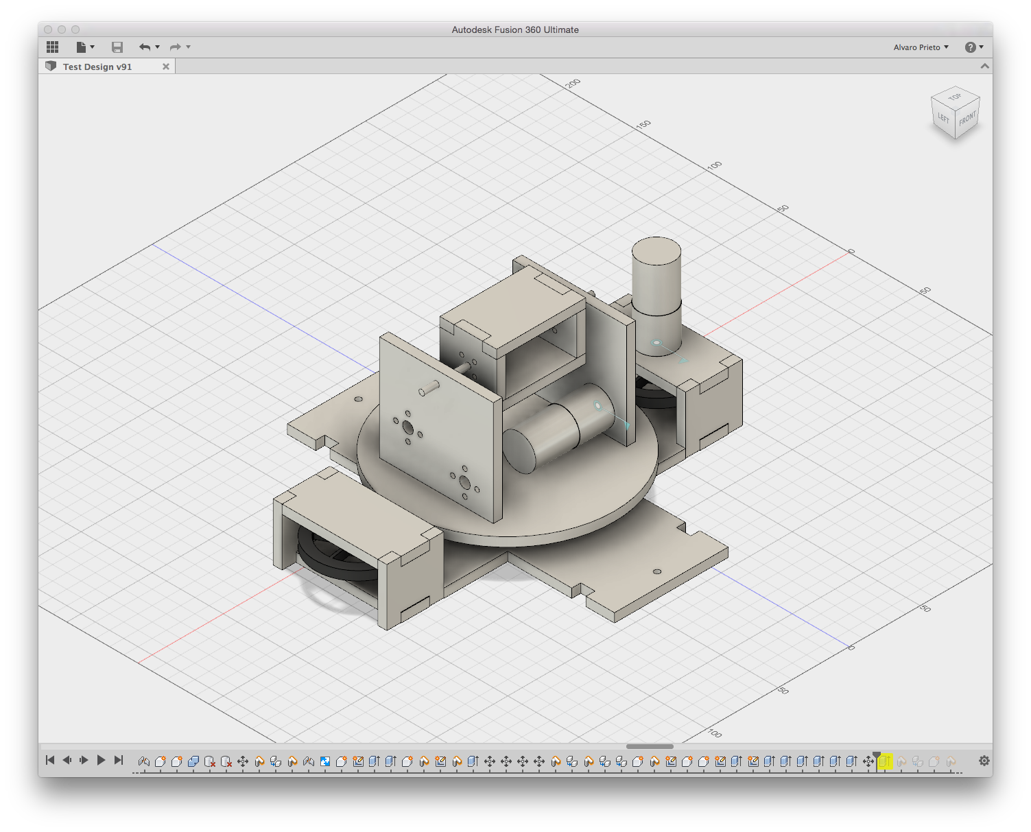
Up to this point, I had been using QCAD to do the mechanical design. I would work in 2D and laser cut the pieces. I found out about Autodesk Fusion 360 and decided to give it a try. Considering I’ve never done 3D CAD work before, it wasn’t terribly hard to figure out. Oddly enough, the hardest part for me ended up being exporting the 2D files for laser cutting…
The geared system was nice, but the laser-cut gears still had lots of backlash. I started thinking about different ways of moving the turret which could be better than gears. The pulley had worked, but not under very high load. Unfortunately, with any configuration, I would have to be moving one of the two motors, which is always the heaviest part.
The solution I came up with had the turret on a turntable with bearings. The turntable supported most of the turret weight so the x-axis motor didn’t need to be too big. I still needed a way of connecting the motor to the turret. One of my ideas was to make the entire platform one huge gear, but since backlash would still be there, I decided against it. The solution ended up being rubber wheels.
Having a circular platform between two rubber wheels allowed continuous movement without having to worry about backlash. The initial design had a motor moving one of the wheels with a free running wheel on the other side. This system would have worked if there was an axle holding the platform in the center. Unfortunately, it did not work so well in practice. When changing directions, the entire platform would shift forward and back since there was nothing holding it in place.
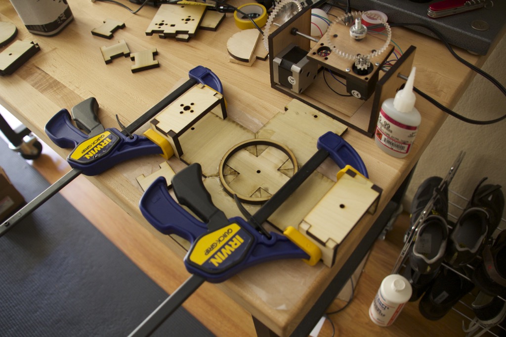
The solution to the problem was obvious: add more wheels! So I did. The next iteration had four wheels to keep the platform in place. This brought it’s own set of problems though. I had been using 4-5’’ wide pieces of wood as my laser cutting material. Since the base was much wider, I had to split it into pieces and epoxy them together. Eventually I bought some MDF from home depot, and cut it as big as the laser cutter could handle (18’’ x 24’’.) This resulted in a more solid base and was quicker to cut and put together.
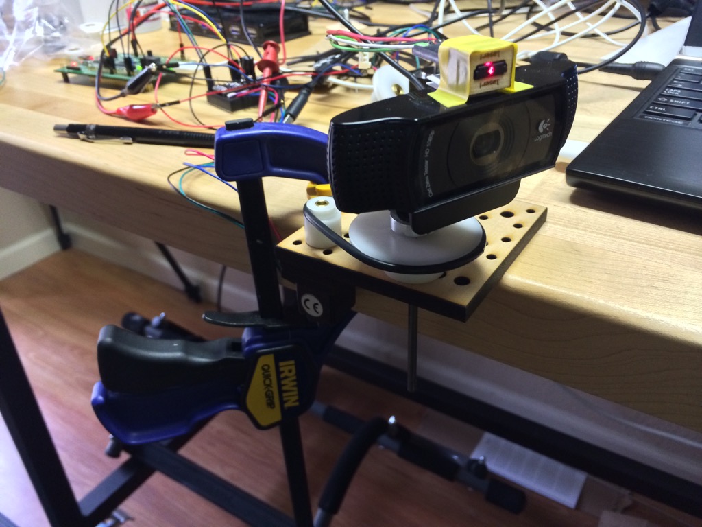
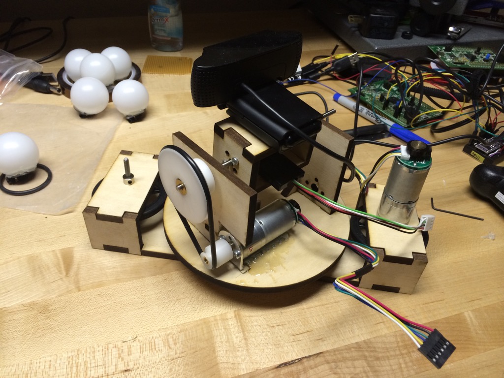
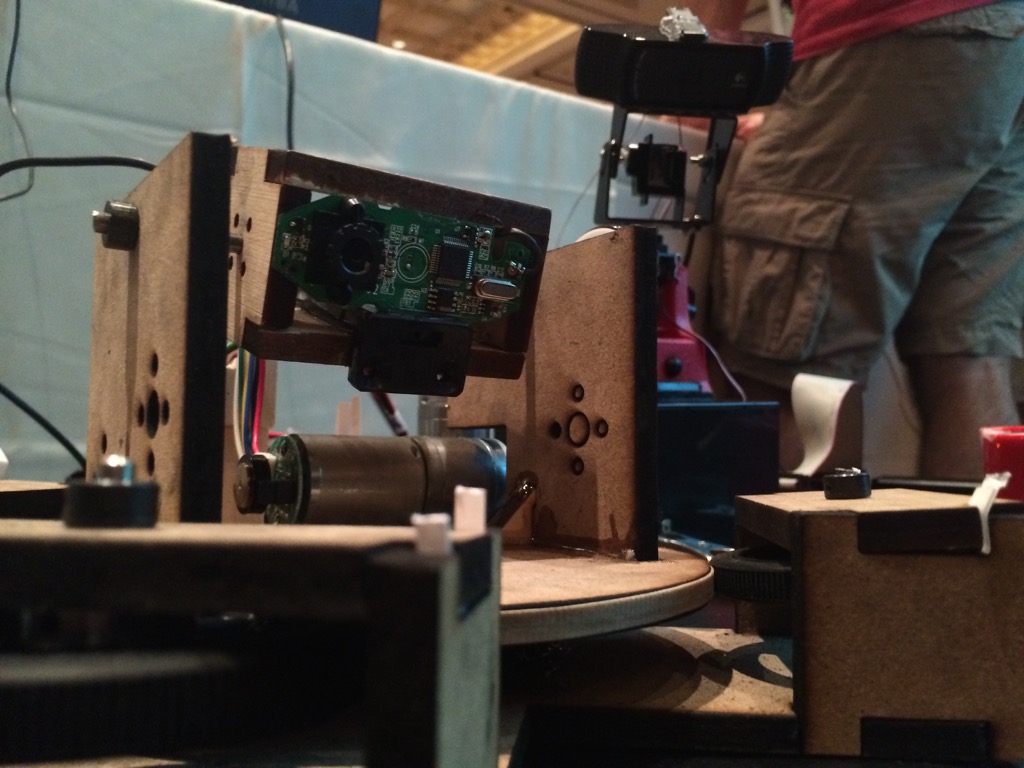
At some point, a friend suggested using gear motors for much better control. I decided to try them out for this new ‘wheeled’ design. They were lighter than the steppers, easier to control, and had better resolution. I tried various gear ratios, but ended up using the 1:172 with a built-in rotary encoder for feedback. Since the y-axis now only had to carry the camera (and not another motor), I was able to use the original pulley/belt system.
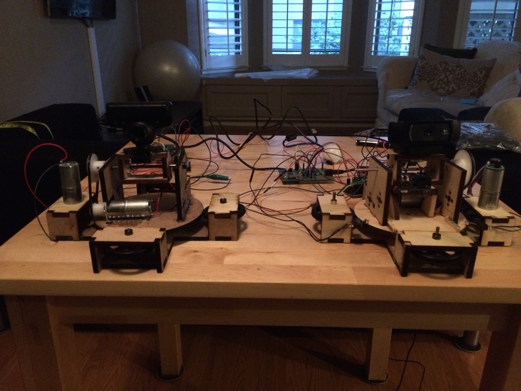
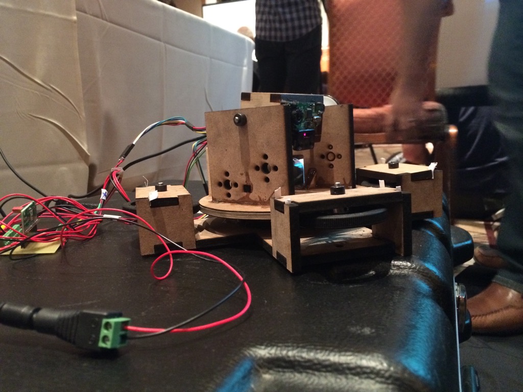
This final design is the one that actually went to DEFCON. During the actual competition, the design showed some of it’s flaws. The wheels didn’t always make contact with the base, so we used paper/cardboard shims to hold them in. This mostly worked, but then the drive wheel started slipping from time to time. The laser cut MDF was covered in burnt powder which made it easy for the wheel to slip. We were able to get some rubber bands to put around the base to increase traction. This also helped in slightly increasing the diameter of the base so all wheels were always in contact. Fortunately, those two fixes were enough to hold it together. The turret went on to win first place for DEFCONBOTS 2014 :D
I started this project with the goal of learning about motor control and mechanical design. Having little-to-no experience with either, I’m pretty happy with the result. I’ll try to do another write up about the firmware/software, which was also lots of fun. For all of the project photos, check out the flickr album.