Laser Turret Progress
Over the past month, I’ve been working on a laser turret for the DefconBots autonomous robot competition this Summer. I entered the same competition back in 2006 and enjoyed the experience, so I figured I’d give it another try. Since I am fairly comfortable wiring firmware, I plan on focusing on the mechanical aspects of this project, as well as the image processing (both of which I know little about.) It should be a fun project and great learning experience. Here is some of the progress I’ve made since I started:
The first thing I did was start from the reference design on the website and bought a laser, servos, and pan/tilt mount for them. I build a very simple controller with an MBED and used a push button and joystick to control. This gave me an idea of the speed/resolution of the servos. (The speed wasn’t completely valid, since there was no heavy webcam to carry).
The servos were quick, but if a target is at the maximum 10m distance, the resolution is not fine enough to track it. Also, all of the weight of the camera is being held up by a tiny servo, which isn’t a great idea.
I thought of a few different designs to try and alleviate this problem, so I went to the hobby shop and bought some materials.The second prototype relieved one of the servos from weight bearing duties and allowed for slightly finer vertical resolution. This one still didn’t have the camera, but I learned a few things about working with balsa wood and cutting metal rods with a hacksaw…
Now that I had a ‘stable’ platform, I decided to attach a webcam to see how it would behave. I ended up choosing a rather heavy one, but it has excellent optics and can be mounted on a tripod. I put on a slightly larger/faster servo, bought a tripod-size screw, and mounted the webcam for testing. The new servo was fast but more often than not, the balsa wood base moved just as much as the camera.
While waiting for some parts I ordered, I decided to try and make some progress in the computer vision department. I installed Ubuntu in an old laptop and spent a few hours getting openCV compiled from source. (Turns out there’s a much easier way. I’m not sure how I missed it the first time…)
I was able to get a quick program that detects circles, picks the largest one, and moves the camera toward it. It worked, but the limitations of the mount were apparent. If the camera moves too far forward, it just falls off, never to return. That being said, the most important lesson from that experiment was: Get a dark, solid background, while testing/debugging your CV algorithm. T-shirts with round shapes are discouraged, as the robot will think you are the target and ignore the real one…
After receiving a large black tablecloth, I set it up and continued testing. Since the final device needs to actually shoot at the targets, I figured I might as well attach a laser to it again. I couldn’t come up with an elegant mounting solution in a short time, so I just used electrical tape and some cut cardboard for support.
The solid background worked extremely well. The robot was no longer focusing on non-targets. After adding some code to only enable the laser when the target was centered, I tested it again. The movement was still choppy, but the detection and shooting worked just as expected.
Since I was still waiting for parts for the next iteration of the mechanical platform, I switched to working on test targets. The organizers were nice enough to provide a target reference design as well. It consists of blue LEDs, red light sensors, and a microcontroller to detect the hits. I only had some of the required parts at home, so I decided to make a slightly simpler version of it.
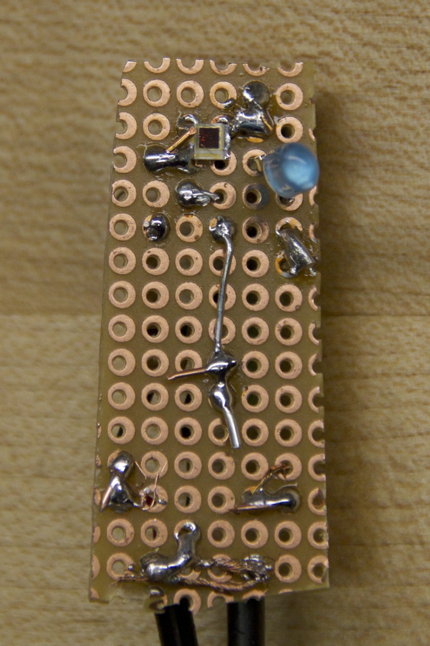
Target Front - Light sensor and blue LED
After testing the light sensor, I decided to mount it on a perf board, along with the blue LED and some resistors. I thought about using old phone cable to take the signals back to the microcontroller doing the measuring, but I found some headphone cables and used them instead. I cut a hole on a ping pong ball, mounted the board inside, hot glued a bunch, and started testing.
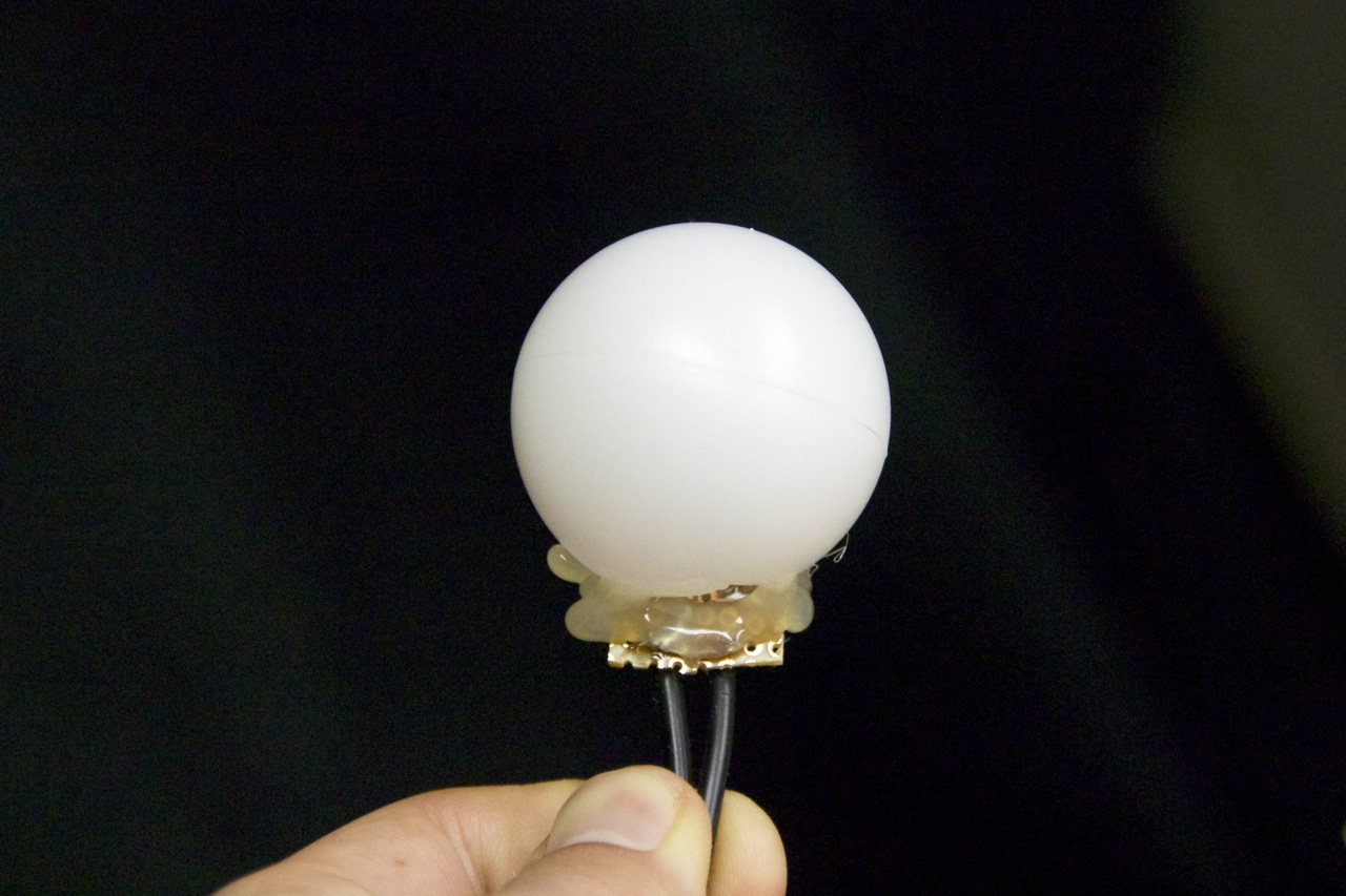
Target
I spent some time getting the microcontroller that’s doing the hit detection working. The code should be fully modular and easily support new targets (once I put them together…) I added a calibration routine so it knows what is ambient light (including that blue LED) and what is a hit. The competition requires the laser to be on-target for 1.5 seconds, I set mine for 0.5 for this quick test.
That’s most of my progress so far. I’ve also been working on other mechanical designs, but I haven’t documented any of them yet. Working on this has been educational and quite fun! Incremental updates are usually on youtube way before I write about them.
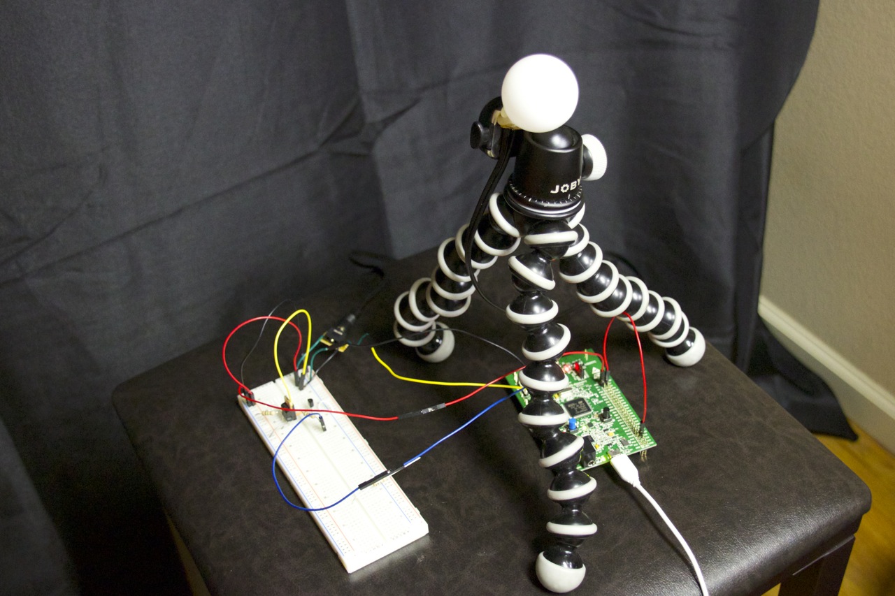
Target setup for testing.