CC2500 Project (Part 8) - Downsizing
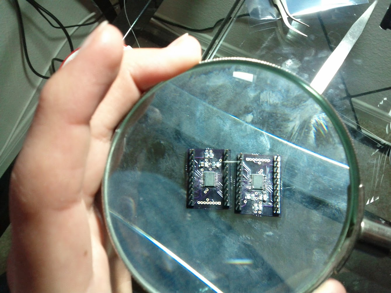
I received my PCB’s yesterday (From Laen at dorkbotpdx.org, of course!). I spent last night attempting to solder all the surface mount components (and for the most part, failing miserably). I need to get some solder paste and a small oven for the next batch…

After soldering all of the passive components and msp430’s, I began the first set of tests. First I checked to see if all of the connections were good with my multimeter. Once I fixed any problems I found there, I tried powering the board and connecting with the programmer/debugger. Surprisingly, it worked almost immediately! (I had to connect power to the correct pins first…)

The next test consisted of flashing the two LED’s. Unfortunately, only one of them worked… I put together two devices, but LED1 didn’t work on either one! I decided to call it a night then. After getting back from work today, I continued my debugging session. Turns out that one resistor wasn’t soldered correctly (my multimeter test worked because I was pressing it down with the probe) and the second was a badly soldered LED.

I continued the same test by toggling all of the IO pins (Port 1 and 2). I looked at each one with the oscilloscope to make sure it was toggling correctly. As soon as I started, things went downhill. Some pins toggled, but most didn’t. I went back and re-soldered all of the msp430 pins and tested them again. It was better, but half of the pins still didn’t toggle. I decided to probe the microcontroller pins directly, but they weren’t doing anything either. It had to be a software problem. It turns out that I was only toggling pins 0-3, and not 4-7. Once I realized my stupid mistake, I corrected it and everything started working.

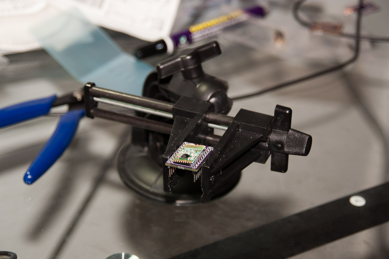
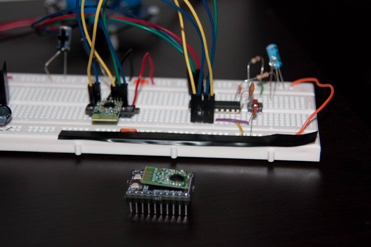
The final step consisted of soldering the CC2500 radios. Unfortunately I didn’t think my design through very well, since the radio modules have the crystal oscillator at the bottom, so it kind of sticks out at an angle. I changed the wireless RGB LED controller code to run on the msp430g2412 (which is what these use) and re-programmed them. Amazingly, the radios worked on my first try.

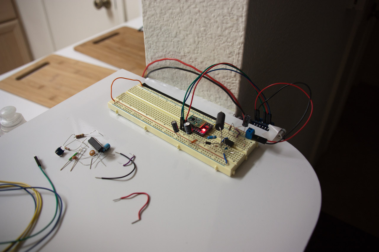
I decided my old RGB LED controllers were taking up too much space on the breadboards, so I replaced them with the newly created modules. They take up very little space and work just as well. I’m thinking of making the switching DC/DC power supply just as small and hopefully integrating it with the current device.

Now that I have a semi-decent platform, I can start working on writing some awesome radio libraries. (Once I put together more radios of course…) I want to have a full home-automation system going in a few months. I’ll keep posting updates here.