After last years DEFCONBOTS competition, I decided to try something completely different. (Check out last year’s robot.) Having to move the entire turret/camera/laser around is incredibly inefficient. If the goal is to shoot things with lasers, the only thing moving should be the laser beam.
Approximation example
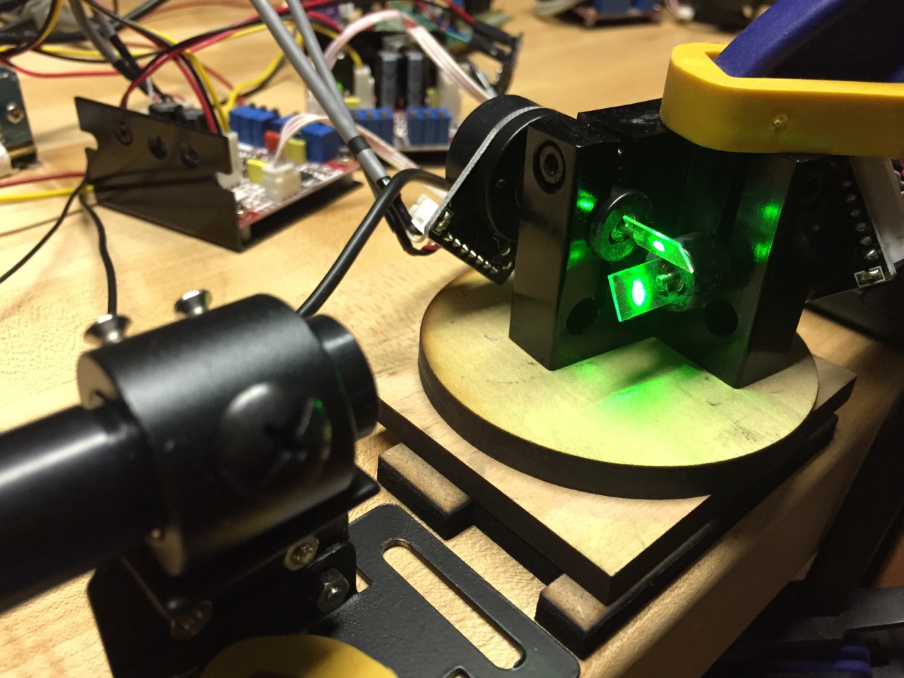
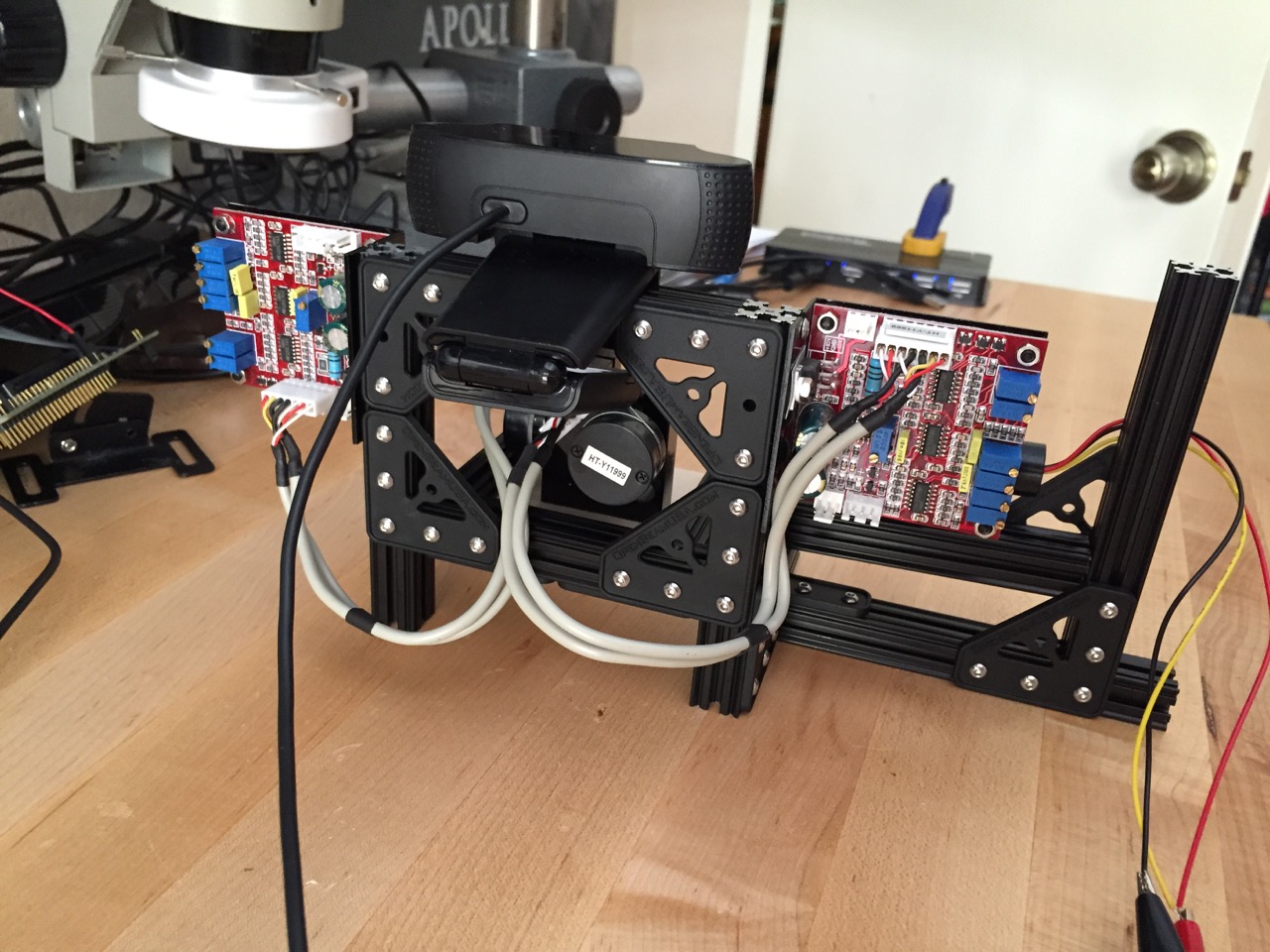
While doing some research, I found various projects with home-made galvanometers. I did not trust myself to actually build something even remotely close to working like that in time for the competition, so I turned to eBay instead. I found some relatively cheap laser show controllers which included two galvanometers (and drivers), along with the mount and mirrors.
Approximation example
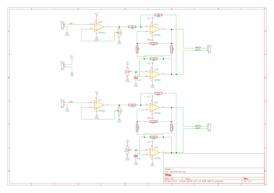
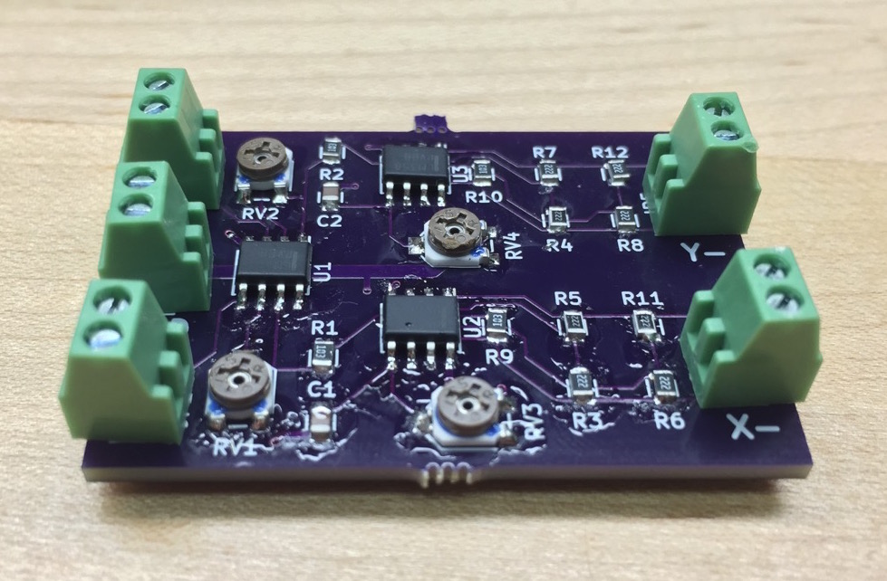
The interface to the laser show controller was poorly documented, but I found out that the galvanometer drivers just took a differential signal of -15V/15V which determined the mirror deflection. That seemed like an easier path than trying to reverse-engineer the controller. I made a board that took my 0-3.3V microcontoller DAC outputs and converted them to a differential signal pair of 0-15V. (Maximum deflection is achieved with a difference of 10V, so there was no need for me to generate negative voltages) It took some messing around with the OpAmp gains to get the system working, but I eventually had a good way to move the laser with my computer (through an STM32F07 microcontroller.)
Approximation example
Approximation example
So now I could move the laser at crazy-fast speeds. Compared to last year’s robot, this one can practically aim anywhere (within the field of view) in milliseconds. The problem was that I had no idea what I was shooting at. Previously, the laser and the camera were mechanically linked, so it was fairly simple to determine where the laser was going to hit relative to the camera. With this system, all that goes out the window.

Approximation example
The camera is now static, which is great for detecting moving targets, but not so great for figuring out where the laser is going to go. If I was a machining/CAD wizard, I could mount the laser, galvanometers, and camera precisely enough that I could use some math to calculate angles/depths and figure out where the laser is going. As I mentioned previously though, I am no CAD wizard, and my mechanical skills are… lacking. With no mechanical solution to the problem, I had to start getting creative with software.
Approximation example
After trying to figure out a way to do this mathematically (and failing), I realized it didn’t have to be perfect. I didn’t really need to be able to shoot the laser at an arbitrary point in space. The system input is a webcam. That’s how the system sees the targets, so all I had to do was come up with a way of correlating the laser position with pixel (x,y) coordinates on the camera. If the camera sees a target at some position, and it knows how to make the laser go to that pixel position, the system should, in theory, work.
The calibration procedure ended up working as follows: A 10x10 grid of points is successively projected on the background surface. For each laser setting(laser x,y position), I saved the position (in pixel coordinates) where the laser showed up. This resulted in a ~100 point lookup table relating pixel positions with laser settings. Here’s a quick video of calibration during development. (The area covered is small since I was still messing with the amplifiers.)
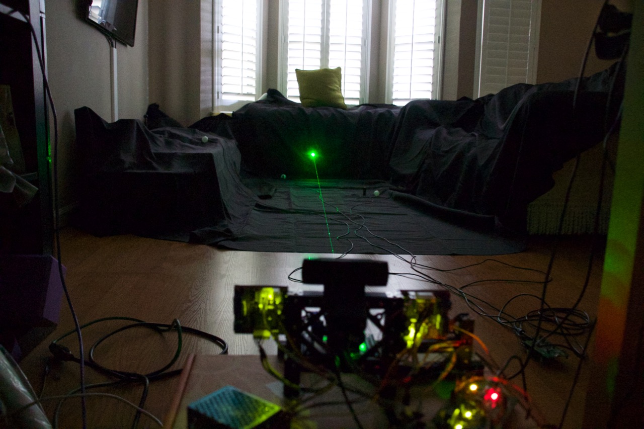
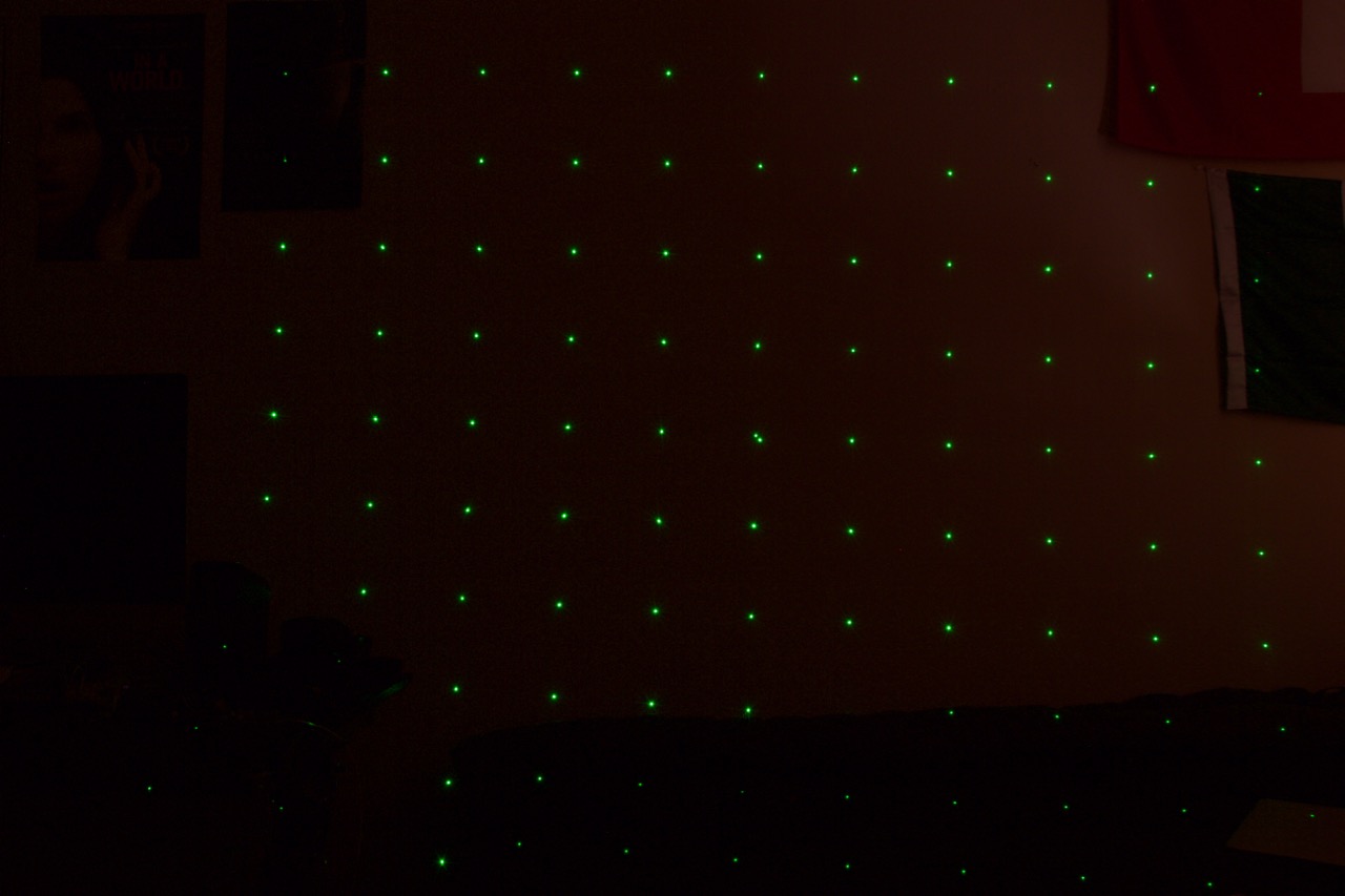
Actually, here’s a long exposure of what it looked like later on:
Approximation example
So now I had a lookup table, but only for a fixed number of values. Technically, I could have scanned the entire surface, but that would have taken too long, as I was limited by the camera’s frame rate. What I ended up doing is a sort of successive approximation to interpolate between the calibration points to get an arbitrary one. For example: I want to shoot at pixel x1,y1. I first find the four closest calibration points from the lookup table. I then proceed to compute the mid-points between the four calibration points (and also average the laser settings between the two). I select the new four closest points (including the virtual, newly computed ones) and repeat. I do this a few times until the new virtual (or real) calibration point is close enough to the desired pixel value. Here’s a visual example of what is happening (The larger red circles are calibration points, the rest are successively calculated midpoints):
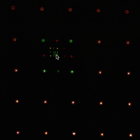
Approximation example
The lookup table with approximation worked great, when testing against a surface (not necessarily flat). I could place the camera virtually anywhere (I tested with it more than a 3 ft separation from the galvos), and after calibration, the laser would go exactly to the pixel I wanted. Unfortunately, things get complicated when you’re trying to hit an object that’s between the background surface and the camera. To minimize the effect this had (since the targets were above the ground), I placed the camera as close as I practically could to the mirrors. Luckily, this was ‘good enough’ in most cases. Here’s an example of click-to-shoot working during development:
Instead of laser-cutting the entire robot this year, I decided to use the openbeam extruded aluminum system to get everything up and running quickly. I’ll do a follow-up post about all the mechanical fun that I had to deal with. For all the vision, we used openCV with python. I’ll also cover that in another post.
As for the results, we got 3rd place overall. The vision and tracking were working, but we had some technical difficulties with the laser shots registering with the targets. Shots consisted 4800 baud serial packets over the laser. I still have to do some investigating to figure out why it wasn’t working. We suspect it was just a bad laser, but it could also have been my power supply, or the dimming due to it bouncing off two mirrors.
I don’t seem to have many good videos during the competition, but here’s one when it was sort of working:
If there are any parts you’d like me to focus on, let me know before I do the next write up and I’ll try to expand on them.