I just spent several hours debugging my cc2500 radio libraries. What changed you might ask? Two lines of code…
My Wireless RGB LED driver had been using the msp430g2452 microcontroller. So far it has been working great! Someone emailed me asking about the msp430g2533, and how it wasn’t quite working. I currently use the msp430g2203 (which is a cheaper variant of the 2533) as my PC-to-cc2500 interface, and it has been working for a while (or so I thought!).
I decided to begin testing the 2533 with the rgb led radio code. As you might expect, it didn’t work. I quickly pulled out my Salae Logic analyzer and connected it to the msp430-to-radio interface to see what was going on. To have an idea of what the signals should look like, I used the 2452. I spent a few hours comparing the two signal captures, measuring timings, read data in the microcontroller, etc… This is a ‘quick’ summary of my findings.
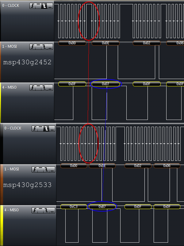
The first thing I noticed was that the separation between the address and data bytes was different between the devices (Circled in red). The 2452 had about 1.58 µs separation while the 2533 only had 0.5 µs. I looked in the cc2500 datasheet and realized that as long as that separation is greater than 55 ns, everything should work, which meant that was not the problem.
Another thing I noticed was that the 2533 misread some of the radio settings. For example, it would read 0x03 instead of the actual 0x07. This suggested something was wrong with the bit timings. After some more messing around, I saw this:

The 2533 was starting the byte transmission half a clock-cycle too early! This also means that it is trying to sample incoming data at the wrong time (which is why some of the data reads were wrong). After digging around in datasheets and code, I found the source of the problem to be this line in the SPI configuration:
UCB0CTL0 |= UCMST+UCCKPL+UCMSB+UCSYNC+UCCKPH; // 3-pin, 8-bit SPI masterThe problem was with the Clock phase select bit (UCCKPH). It was set to capture data on the first clock edge and change on the following edge. Clearing that bit configures it to change data on teh first clock edge and capture on the following edge.
So that fixed the communication problem, but there was still a problem. The first setting written to the c2500 after reset was not being saved. Looking at the earlier capture (Blue circles in first image), the cc2500 returns a status byte of 0x87, instead of 0x07. The MSB in this case means that the radio is not ready. The problem here ended up being in the cc_powerup_reset function. Turns out the function wasn’t waiting for the device to actually reset (just sending the reset command), so that first setting write happened while the radio was still restarting.
You can see the actual fixes in this git commit.
Not sure if you noticed, but I did mention that the msp430g2203 was previously working with the same (broken) code. My theory for this is that all it ever did was transmit data, so it never ran into the receive problems. Also, the mis-aligned data might have been read properly by the cc2500. Another thing was that the first setting that wasn’t saved wasn’t really important, so I never noticed. I’m glad I figured this out before trying to receive any data on the 2203…
Now that my radio library works with both devices that have USI (msp430g2xx2) and USCI (msp430g2xx3), I can start using them to make some more interesting gadgets.