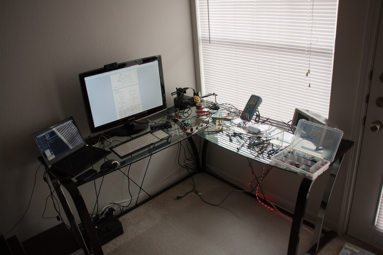
Here’s another quick update (with lots of pictures and a video!) I ordered another RGB LED strip from adafruit in order to test how my system works with multiple devices. I don’t have my PCB’s yet (I shipped them to NY by mistake…), so I had to build everything on breadboards.
The main problem with my previous design is that it required two separate power supplies. The LED strip runs off 12v, while the microcontroller and radio run at 3.33v. I had a couple of MC34063A DC/DC converters laying around, so I figured I’d make a 12-3.3v converter. I also had an LD33V linear regulator, so I decided to try them both.

Unfortunately, I didn’t have the exact parts required to make the switching regulator, so I had to use the closest available. This produced an extremely noisy (± 400mV) output, which resulted in a non-working microcontroller. I was able to temporarily solve the problem with some decoupling capacitors, but I still need to get the right parts to make it more stable. What happened was that the microcontroller would start and then just hang or reset at random. At first I thought it was a code issue, but then I looked at the power supply… I’m glad I bought an oscilloscope, otherwise this problem would have been pretty hard to solve.
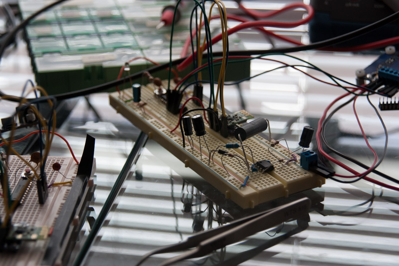
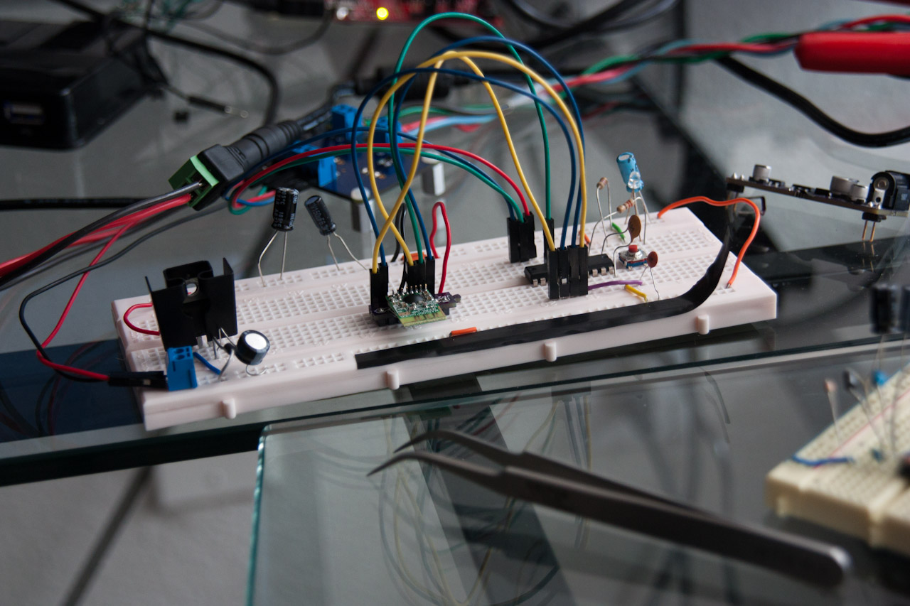
Since the DC/DC converter was not behaving too well, I decided to use the linear regulator with the other circuit. Dropping 12v to 3.3v with a linear regulator produces a lot of heat. I had to get a heat sink, otherwise I would burn my hand if I touched it. It’s a huge waste of power, but it works for now…
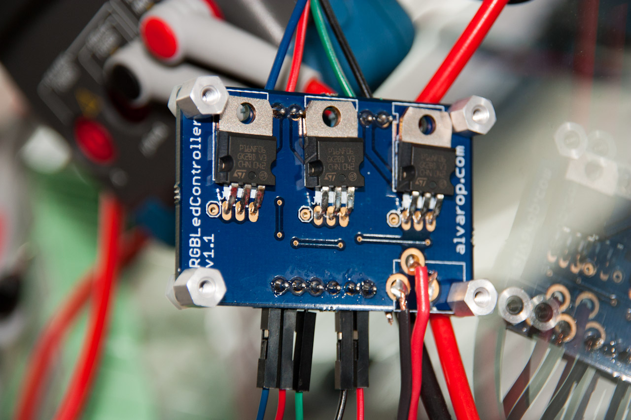
In order to drive the second LED strip, I had to put together another RGB LED driver board. It’s just three MOSFETs, along with some resistors and BJT’s to drive them. I connect the 12v power supply directly to these, and then connect it to the microcontroller board’s power supply. The next thing to do will be to have them all on the same PCB…
So what did I end up doing with these? Well, I put one on top of a shelf, and the second under… Ok, I don’t know what it’s called. It might be a kitchen counter-top, but I’m not sure. Here are some photos that will hopefully make more sense.
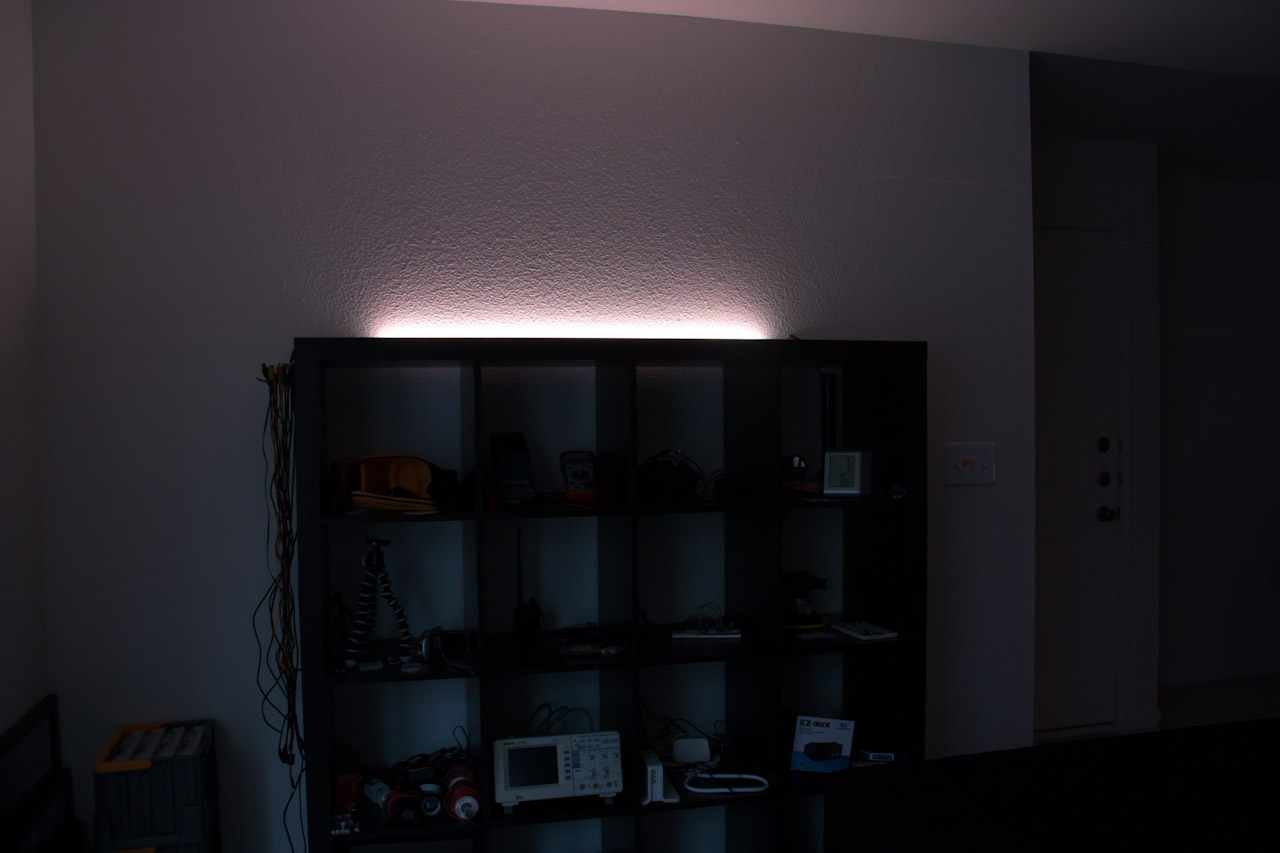
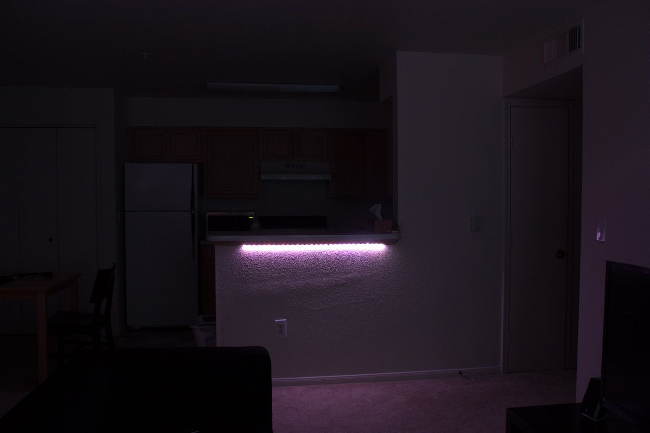
I tried getting a video of the whole setup, but my camera doesn’t seem to like low light situations. It looks much better in person!