I made a remote trigger using an MCT6 Optocoupler, some buttons, LED’s, and 2.5mm stereo jack.
This will hopefully be able to connect to a microcontroller to take pictures at set intervals. By using the 2.5mm connector, this device should also work with the Canon EOS DSLR cameras. (Which I don’t have, but I’ll find one to test this on…)
Here are some details…

Opening the HP camera was more complicated than I expected. I had to remove about 15 screws, disconnect several ribbon-cables, and use more force than I am comfortable with with circuit boards. Eventually I got to the shutter button.
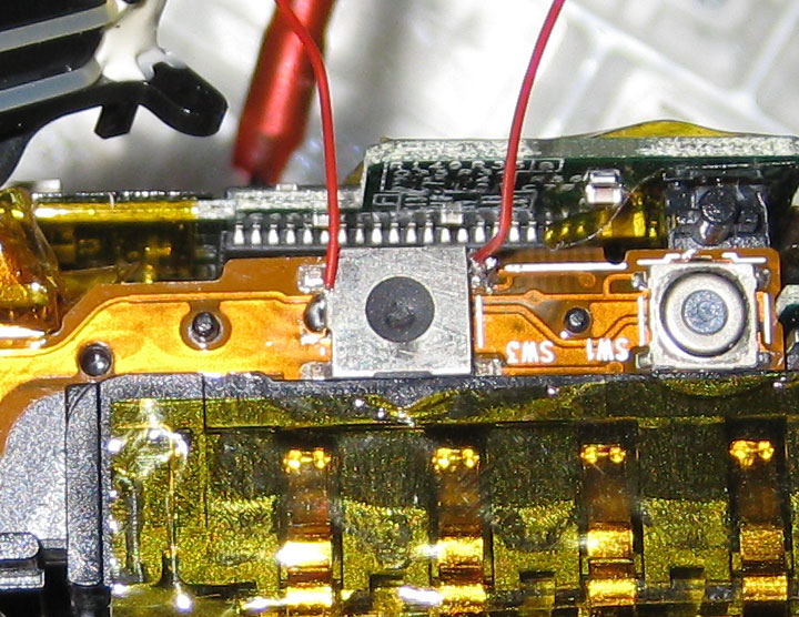
The shutter button has two different pressing modes. When you press the button down lightly, the camera focuses, and once you press it all the way down, it takes the picture. I used my multimeter to figure out which pins did what. I figured out that there one pin is connected to ground, the second to the focus trigger and the third to the shutter trigger.
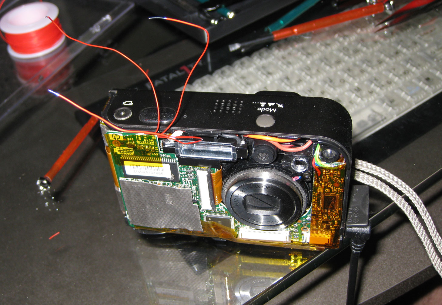
Once I soldered some very thin wires to the button pins I spent some time putting the camera back together. I had to make a small hole in the top so the wires wouldn’t be cut by the front cover.
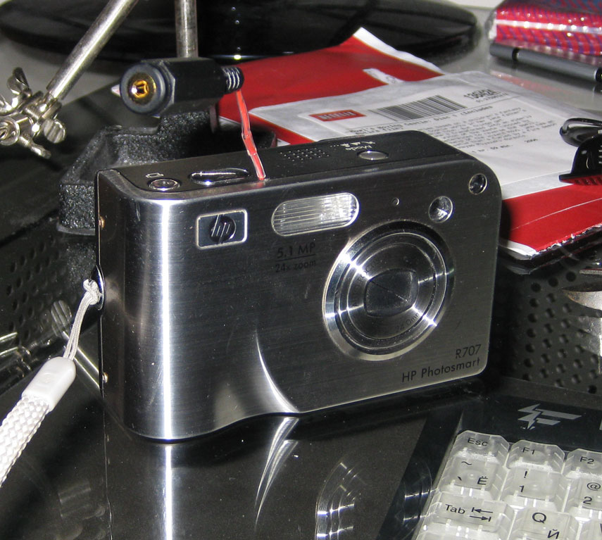
Once I closed it, I soldered the wires to a 2.5mm female stereo connector. This is also used by the Canon DSLRs, so I figured it was a good idea to use it, since I’m planning to upgrade. I also used some heat-shrink tube to protect the tiny wires from breaking too easily.
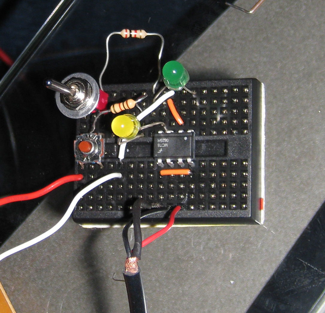
After the camera was all set, I made a small circuit to trigger the camera. I used an MCT6 optocoupler from Fairchild Semiconductors to isolate the camera from the rest of the circuit. I then connected two button/switches that I found lying around, two resistors, and two LED’s to show when each is enabled. The bottom cable assembly with three wires coming out is a 2.5mm male stereo jack that connects to the camera. The left red/white wires come from a homemade 5V power supply.
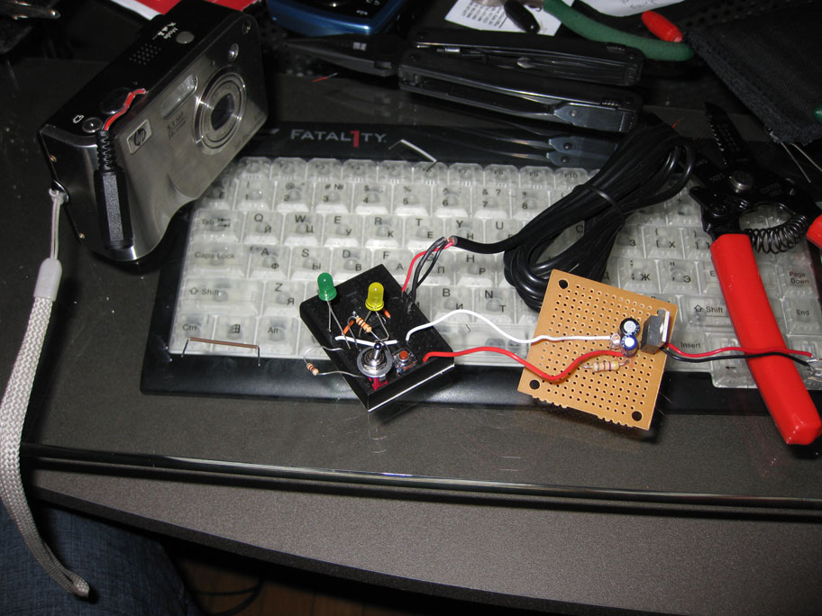
The full setup can be seen here. The circuit on the right is just a 5V regulator with some filtering capacitors I use for various projects.
The main goal of this project was to test the optocoupler and circuit before I test it with a much more expensive DSLR. I also wanted to see what was inside my old digital camera. Now that this works, I can connect it to a microcontroller and use it for long term time-lapse shots.
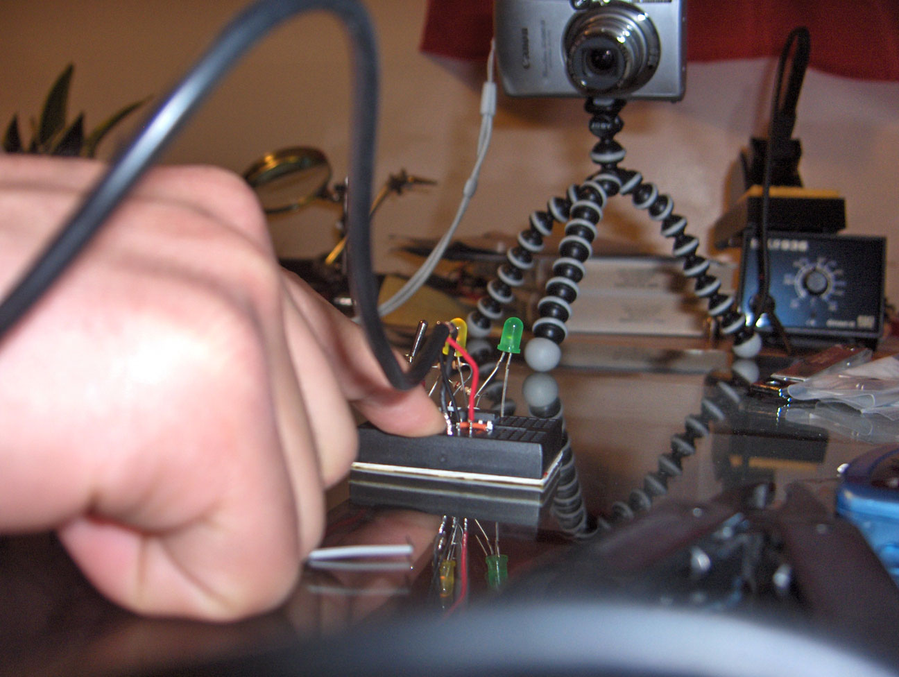
Here is a [bad]video of me explaining how it works.
This is the picture that was taken while making the video. The camera in the background on the gorillapod was recording the video.
Thanks to http://als-project.blogspot.com/2009/03/trigger-time.html for the pin-out for the canon trigger.